Проверка
Проверка
Проверка
Проверка
Проверка
Проверка
Integrating a stepper motor with a limit switch using an Arduino is a fundamental skill for many automation and robotics projects. This setup ensures precise control over the motor's movement, allowing it to home to a specific position reliably. Whether you're building a CNC machine, a 3D printer, or an automated camera slider, understanding this combination is crucial. This guide provides a clear, step-by-step approach to wiring, programming, and implementing this system effectively.
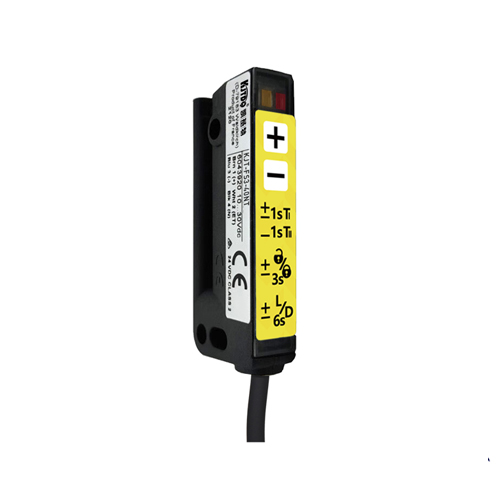
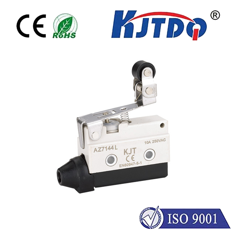
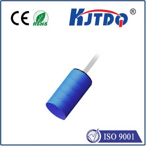
First, let's understand the core components. A stepper motor moves in discrete steps, offering excellent positional accuracy. Unlike standard DC motors, you can control its rotation angle and speed precisely by sending digital pulses. A limit switch is a simple sensor that acts as a physical "stop" button. When an actuator (like the motor's carriage) presses the switch, it changes its electrical state, signaling the Arduino that a boundary has been reached. The Arduino Uno, a popular microcontroller board, serves as the brain, reading the switch and controlling the motor driver.
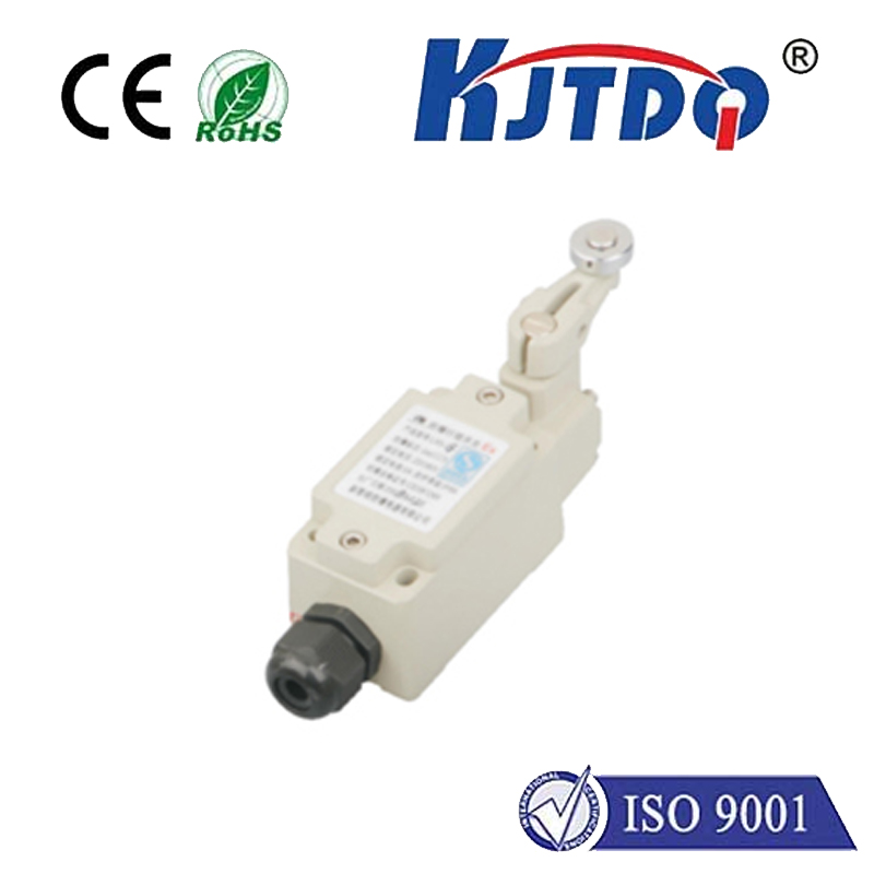
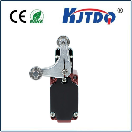
For this project, you will need an Arduino board (Uno is ideal), a stepper motor (a common NEMA 17 is used here), a compatible stepper motor driver module (like the A4988 or DRV8825), a limit switch (mechanical or optical), a power supply suitable for your motor, jumper wires, and a breadboard for connections. Always ensure the power supply matches your motor's voltage and current requirements to prevent damage.
The wiring process is straightforward but requires attention. Connect the stepper motor coils to the output pins of your driver module. The driver's step and direction pins connect to two digital pins on the Arduino (e.g., pins 2 and 3). The limit switch has three terminals: common (COM), normally open (NO), and normally closed (NC). For a simple active-low setup, connect the COM terminal to the Arduino's ground (GND) and the NO terminal to a digital input pin (e.g., pin 9). Don't forget to use a pull-up resistor internally (via code) or externally on the input pin to ensure a stable reading when the switch is open. Finally, provide appropriate power to the driver module and Arduino separately.
The core logic of the Arduino code involves two main states: seeking the limit and normal operation. The program typically starts by moving the motor slowly towards the limit switch. It constantly reads the state of the switch's input pin. When the switch is pressed, the pin state changes (e.g., goes from HIGH to LOW), and the Arduino immediately stops the motor. This position is now defined as "home" or zero. After homing, the motor can then move accurately to any other position within its travel range, knowing its exact starting point. A basic sketch uses theAccelStepper library, which simplifies control. The code initializes the stepper object, sets a maximum speed, and then runs a homing routine where the motor moves until the switch is triggered. After that, it can be commanded to move a specific number of steps relative to the home position.
A common challenge is switch "bouncing," where the mechanical contacts cause rapid on-off signals during activation. This can confuse the Arduino, making it think the switch was pressed multiple times. The solution is to implement "debouncing" in the software. After detecting a switch press, the code should wait for a few milliseconds (a debounce delay) to ignore any further fluctuations before confirming the state. This ensures a single, reliable trigger. Another tip is to always approach the limit switch at a slow, consistent speed to avoid overshoot and mechanical impact, which could damage the switch or the motor assembly.
The applications for this setup are vast. In 3D printers, limit switches define the boundaries of the X, Y, and Z axes, ensuring every print starts from a known location. In automated stages or linear actuators, it provides repeatable homing for complex movement sequences. You can expand the system by adding a second limit switch at the opposite end to define a full range of travel, enabling even more robust control. Experimenting with different types of switches, like optical or hall-effect sensors, can offer non-contact sensing for higher precision or durability.
By mastering the connection between a stepper motor, a limit switch, and an Arduino, you unlock a higher level of control for your mechatronic projects. The process reinforces key concepts in sensor integration, real-time input monitoring, and precise motion control. Start with the basic wiring and code provided, ensure your homing routine is reliable, and then integrate this subsystem into your larger project. Remember to test frequently and make incremental changes to your code and hardware for the best results.