Датчики приближения pnp и npn
- time:2025-06-25 02:28:22
- Нажмите:0
Proximity Sensors Demystified: Understanding PNP vs. NPN Wiring and Applications
That moment when you’re wiring a proximity sensor: you’ve got the perfect spot, the mounting is secure, and then… you stare at the wires. Blue, brown, black… and a cryptic datasheet mentioning PNP or NPN. Choosing the wrong one can mean a sensor that stubbornly refuses to work or even risks damaging your system. Fear not! This fundamental distinction boils down to how the sensor switches its output signal to interact with your control system. Grasping the difference between PNP and NNP is crucial for seamless integration and avoiding costly headaches.
The Core Function: Switching the Load
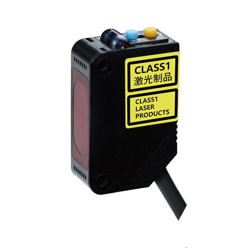
At its heart, a 3-wire DC proximity sensor (inductive, capacitive, or photoelectric) is an electronic switch. It needs a power supply (typically 10-30V DC) – usually provided via the Brown (Positive +) and Blue (Negative -) wires. The critical third wire, often Black (or sometimes White or Grey), is theoutput signal wire. This is where the PNP or NPN designation comes into play. It defines the electrical behavior of this output when the sensor detects a target (its “on” state).

PNP: The Positive-Switched Sensor (Sourcing)
- How it Works: Imagine the PNP sensor’s output acting like a switch connected to the positive voltage supply (Brown wire).
- No Target: The output switch is OPEN. The black wire is disconnected internally from the positive supply. No positive voltage is present on the black wire relative to blue (negative).
- Target Detected: The output switch CLOSES. The black wire is now connected internally to the positive supply (Brown). Positive voltage (+V) appears on the black output wire relative to the blue wire (negative).
- The Result: When active (target detected), the PNP sensor sources positive current out of its black wire. This positive current flows into the input point of the connected load device (like a PLC input module, relay coil, or indicator light).
- Analogy: Think of the PNP output as a tap connected to a water tank (positive supply). When open (target detected), water (positive current) flows out of the tap (black wire).
NPN: The Negative-Switched Sensor (Sinking)
- How it Works: Conversely, the NPN sensor’s output acts like a switch connected to the negative voltage supply (Blue wire).
- No Target: The output switch is OPEN. The black wire is disconnected internally from the negative supply (Blue). Essentially, the output is “floating” (though sometimes pulled high internally).
- Target Detected: The output switch CLOSES. The black wire is now connected internally to the negative supply (Blue). The black output wire effectively becomes connected to 0V (ground), sinking any positive voltage applied to it.
- The Result: When active (target detected), the NPN sensor provides a path to ground (negative) for current flowing into its black wire. Current flows from the positive side of the load device, through the load, and into the sensor’s black wire, down to ground (Blue).
- Analogy: Think of the NPN output as a drain connected to the sewer (negative/ground). When open (target detected), it allows water (current) to flow into it from a source (the load device).
Visualizing the Difference: A Simple Circuit
Consider a simple circuit with a sensor, a load (like an LED with a resistor), and a power supply.
- Sensor Brown (+) to Supply +V
- Sensor Blue (-) to Supply 0V (GND)
- Sensor Black (Output) to Anode (positive side) of LED/Resistor
- Cathode (negative side) of LED/Resistor to Supply 0V (GND)
- Sensor activates: +V from Black flows into the LED anode, through it and the resistor, to GND. LED lights.
- NPN Setup:
- Sensor Brown (+) to Supply +V
- Sensor Blue (-) to Supply 0V (GND)
- Sensor Black (Output) to Cathode (negative side) of LED/Resistor
- Anode (positive side) of LED/Resistor to Supply +V
- Sensor activates: Black wire connects the LED cathode to GND. Current flows from Supply +V, through the LED/Resistor, into the Black wire, down to GND. LED lights.
Why Does PNP vs. NPN Matter? Compatibility is Key!
The choice isn’t about one being universally “better,” but about matching the sensor’s output type to the input requirements of your control device (PLC, relay, counter, etc.).
- PLC Input Modules:
- Most modern PLCs offer modules compatible with both PNP (sourcing) and NPN (sinking) sensors. Crucially, you must configure the module correctly or choose the right module type.
- А.Sinking Input Module on a PLC is designed to accept current sourced from an external device. It requires a PNP sensor (which sources positive current).
- А.Sourcing Input Module on a PLC is designed to provide current that an external device must sink. It requires an NPN sensor (which sinks current to ground).
- Mixing incorrectly (e.g., NPN sensor into Sinking Input) will result in no signal.
- Voltage Levels: Ensure the sensor’s output voltage when active (+V for PNP, near 0V for NPN) matches the logic level expectations (“high” or “low” = true) of your control input.
- Regional Preferences: While not a hard rule, PNP sensors (sourcing) are often more common in Europe and for many modern PLC systems, while NPN (sinking) can be prevalent in older systems or specific regions like Japan. Always check your specific controller’s documentation.
- Wiring Considerations: Understanding the current flow path (sourcing vs sinking) is essential for designing the overall circuit, especially when using relays or interfaces between different voltage domains.
Making the Right Choice and Troubleshooting Tips
- Consult the Controller Manual: This is paramount! Identify whether your PLC input module (or other device) is configured for Sinking (needs PNP) or Sourcing (needs NPN) inputs.
- Check Sensor Datasheet: Explicitly confirm the sensor’s output type (PNP or NPN) and its voltage/current ratings.
- Visualize the Current Path: Think through where the current needs to flow to activate the load when the sensor detects a target.
- Common Troubleshooting for No Signal:
- Power: Is Brown (+V) and Blue (0V/GND) correctly connected and is power present?
- Sensor State: Is the sensor actually detecting the target (check indicator LED if present)?
- Wiring: Is the Black output wire connected to the correct point on the load relative to the sensor type?
- Mismatch: Is there a fundamental PNP/NPN incompatibility between sensor and load?
- Load Compatibility: Does the load (e