измерение скорости вращения датчика приближения
- time:2025-06-25 02:23:25
- Нажмите:0
Beyond Contact: How Proximity Sensors Deliver Unmatched RPM Measurement Precision
Imagine the relentless spin of a massive turbine, the whirring heart of a high-speed conveyor, or the critical rotation inside a precision pump. Knowing the exact rotational speed (RPM) of these components isn’t just data; it’s the pulse of the machine, vital for performance, safety, and predictive maintenance. While physical tachometers have their place, non-contact RPM measurement using proximity sensors stands as the modern, robust, and highly accurate solution for demanding industrial environments. This technology unlocks insights where direct contact is impossible, impractical, or hazardous.
Why RPM Matters: The Heartbeat of Rotation
Rotational speed is a fundamental parameter. It dictates everything from machine efficiency and output quality to early warning signs of impending failure. An unexpectedly high RPM might indicate an overload slip or control system malfunction, while a sluggish rotation could signal bearing wear, friction issues, or motor problems. Accurate, continuous RPM monitoring allows for:
- Precise Process Control: Ensuring mixers, centrifuges, and conveyors operate at optimal speeds for desired results.
- Condition Monitoring: Detecting deviations from baseline RPM that signal misalignment, imbalance, or component degradation.
- Safety Shutdowns: Preventing catastrophic overspeed situations in turbines, engines, or critical drives.
- Performance Optimization: Fine-tuning equipment for maximum output and energy efficiency.
The Proximity Sensor: Your Non-Contact RPM Sentinel
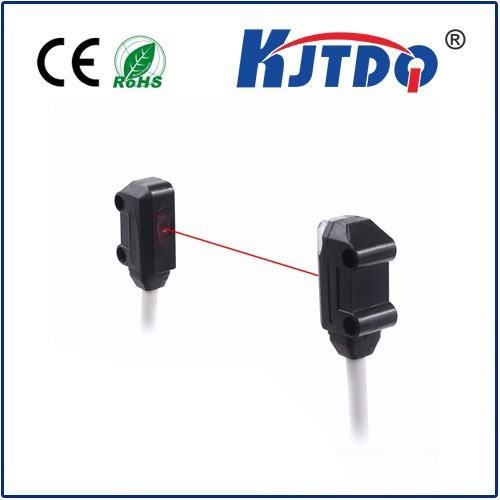
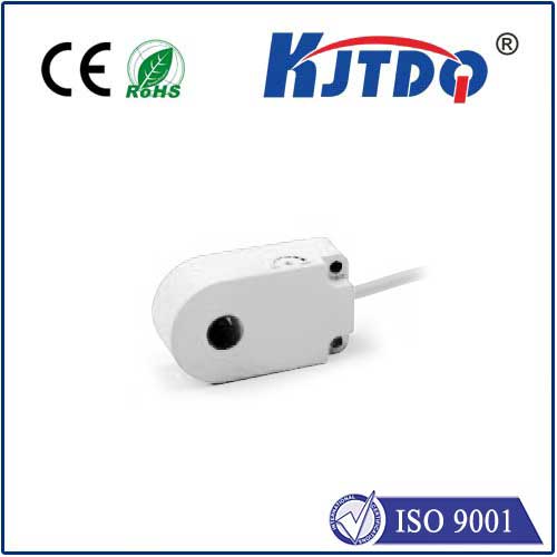
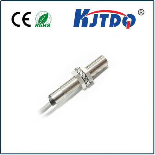
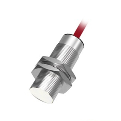
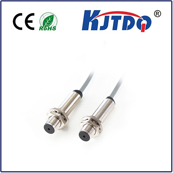
Proximity sensors, particularly inductive proximity sensors, are the workhorses of modern industrial sensing. They detect the presence or absence of metallic objects without any physical contact. This inherent characteristic makes them perfectly suited for RPM measurement on rotating shafts, gears, or components. Here’s the core principle:

- The Target: A feature on the rotating element – often a simple bolt head, a keyway, a dedicated metal tag, or teeth on a gear. This target needs to be made of ferrous metal (like steel or iron) for standard inductive sensors.
- The Sensor: Mounted close (within its specified sensing range or gap) to the path of the target.
- Detection: As the target passes by the sensor’s face, it disrupts the sensor’s electromagnetic field.
- Signal Generation: This disruption causes the sensor’s internal oscillator to shift, triggering its output circuit to switch state (e.g., from 0V to 24V).
- Pulse Train: Each target passage results in one distinct electrical pulse output from the sensor. The key is that one pulse per revolution (PPR) is generated if there’s one target per rotation.
The Magic Formula: From Pulses to RPM
The core simplicity and brilliance of proximity sensor-based RPM measurement lie in translating this pulse train into rotational speed.
- Pulse Counting: The pulses generated by the sensor are fed into a processing unit – this could be a dedicated RPM meter, a Programmable Logic Controller (PLC), a Frequency-to-Voltage converter, or data acquisition (DAQ) hardware/software.
- Time Measurement: The device measures the time between consecutive pulses (pulse period) or counts the number of pulses received within a fixed time window (Частота).
- The Calculation: The fundamental relationship is:
RPM = (Pulses per Time Period) / (Pulses per Revolution) * (Conversion Factor) OR
RPM = 60 / (Pulse Period in seconds * Pulses per Revolution)
Crucially, Pulses per Revolution (PPR) is determined by the number of targets passing the sensor during one full rotation. A single bolt head equals 1 PPR. A gear with 60 teeth equals 60 PPR.
Why Proximity Sensors Rule in RPM Measurement
Choosing a proximity sensor for RPM offers compelling advantages over contact methods (like mechanical tachometers) or other non-contact options (like optical encoders):
- Non-Contact Operation: Zero physical wear on the sensor or the rotating component, ensuring longevity and eliminating slip issues. No lubrication concerns or added friction.
- Robustness: Inductive proximity sensors are inherently rugged. They excel in harsh industrial environments – impervious to dust, dirt, oil, grease, moisture, vibration, and temperature fluctuations where optical sensors might fail.
- Simplicity & Cost-Effectiveness: Relatively simple installation requiring only the sensor, a target, and signal processing. Often more economical than complex encoder setups.
- High Reliability: Fewer moving parts and sealed designs lead to dependable performance over long periods with minimal maintenance.
- Многогранность: Target creation is often simple (using existing features like bolts or adding a small tag), making retrofitting existing equipment straightforward. Sensors are available in various sizes, shapes, and connection types for diverse mounting needs.
- Suitability for High Speeds: Can effectively measure very high rotational speeds where mechanical contact is impossible.
Critical Considerations for Accurate Measurement
Maximizing the accuracy and reliability of your proximity sensor RPM system requires attention to detail:
- Sensor Selection: Choose an inductive sensor appropriate for the target material (ferrous/non-ferrous – though ferrous is standard), required sensing distance, operating temperature range, and output type (PNP/NPN, NAMUR, Analog).
- Target Design: Ensure targets are large enough and made of suitable material to reliably trigger the sensor. For high resolution (more PPR), use multiple equally-spaced targets or a gear.
- Precise Mounting: The sensor-to-target gap is paramount. Install securely according to the sensor’s datasheet specifications. Vibration can cause fluctuating gaps and inaccurate readings if not mounted rigidly.
- Signal Processing: Match the processing unit to the application. Simple RPM meters work for basic monitoring, while PLCs or DAQ systems enable integration into control logic, data logging, and complex analysis. Ensure the processor can handle the maximum expected pulse frequency (Pulses Per Second = PPR * RPM / 60).
- Electrical Noise: In electrically noisy environments, use shielded cables and ensure proper grounding practices to prevent signal interference. Signal isolation is often recommended for DAQ systems.
Beyond the Basics: Advanced Insights
Proximity sensor RPM data is powerful not just for instantaneous speed:
- Continuous Monitoring: Plots RPM over time, revealing trends and transient events.
- Vibration Correlation: Simultaneous RPM and vibration analysis allows for synchronous averaging, pinpointing vibration faults at specific frequencies relative to shaft speed.
- Start-Up/Shutdown Profiling: Capturing acceleration/deceleration rates provides valuable insights into motor performance and load characteristics.
- Overspeed Detection: Critical safety function for preventing equipment damage.
In the relentless drive for operational excellence, proximity sensor RPM measurement provides an elegantly simple, incredibly robust, and highly accurate solution. By translating the silent passage of metal targets into a stream of precise electronic pulses, these sensors deliver the critical rotational speed data that underpins predictive maintenance, process control optimization, and overall equipment reliability. Forget intrusive contact; embrace the power of non-contact sensing and unlock a deeper understanding of your machinery’s vital rhythms.