In the world of DIY electronics and robotics, achieving precise and reliable motion control is a fundamental challenge. Whether you're building a 3D printer, a CNC machine, or an automated camera slider, you need your moving parts to know where they are and when to stop. This is where the powerful trio of an Arduino microcontroller, a stepper motor, and a simple limit switch comes into play. This guide dives deep into how to integrate these components to create robust systems with defined boundaries, preventing damage and ensuring repeatable accuracy.
A stepper motor is an excellent choice for controlled movement because it rotates in discrete steps, allowing for precise positioning without the need for a feedback sensor in open-loop systems. However, an open-loop system has a critical flaw: if the motor misses steps due to excessive load or high speed, the Arduino's internal count of the motor's position becomes inaccurate. Over time, this can lead to the mechanism trying to move beyond its physical limits, potentially causing breakage or failure.
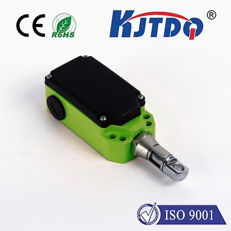
This is the primary role of the limit switch. It acts as a physical sentinel, a simple digital sensor that provides an absolute reference point. Typically a mechanical switch placed at the "home" or end of a travel path, it is triggered when the moving part contacts it. By wiring this switch to a digital input pin on the Arduino, your code can receive a definitive signal: "The axis has reached this known location." From this reference, all other positions can be calculated accurately, resetting any positional drift.
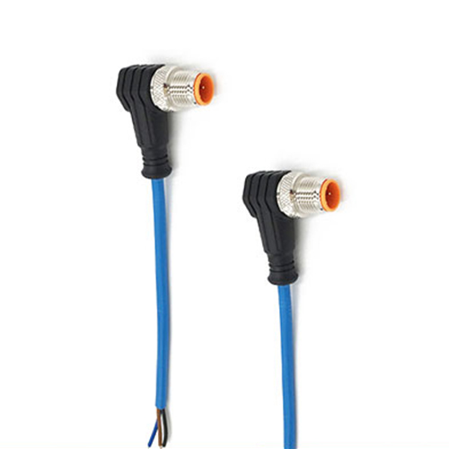
Let's explore the practical wiring. A standard two-wire limit switch (often NO - Normally Open) is commonly used. One wire connects to a chosen Arduino digital pin (e.g., pin 2), and the other connects to the Arduino's ground. A pull-up resistor (either the Arduino's internalINPUT_PULLUP or an external 10kΩ resistor) is crucial. When the switch is not pressed, the input pin readsHIGH. When the moving part presses the switch, it closes the circuit to ground, and the pin readsLOW. ThisLOW signal is your "limit reached" trigger.
For the stepper motor, you will need a driver module like the ubiquitous A4988 or DRV8825. This module connects to the Arduino's digital pins for step and direction control and manages the high current required by the motor from a separate power supply. The critical safety practice is to ensure the motor power supply ground is connected to the Arduino ground, establishing a common reference.
The real intelligence lies in the Arduino sketch. The code must manage two main tasks: moving the motor and constantly checking the state of the limit switch. A typical homing routine works as follows: The motor is commanded to move slowly in the direction of the limit switch. The code continuously monitors the switch's pin in a loop. As soon as the pin goesLOW (switch pressed), the motor immediately stops. For extra precision, the motor might then back off slowly until the switch is released (HIGH), settling at the exact moment of contact release. This position is then set as "zero" in the program. All subsequent movements are relative to this calibrated home.
Beyond simple homing, limit switches are vital for end-stop protection. You can place switches at both ends of travel. Your movement logic should always check that a move command won't drive the motor into a limit. If a limit is active during an operation, it indicates an error or a need to re-home the system. Implementing debouncing in your code for the switch input is also essential, as mechanical switches can "bounce" electrically when pressed, sending multiple rapid signals. A short delay (e.g., 10-50 milliseconds) after detecting a state change ensures you read a stable signal.
Consider a project like an automated drawer opener. The stepper motor drives a lead screw that pushes or pulls the drawer. A limit switch at the closed position tells the Arduino when the drawer is fully shut. Another at the open position prevents it from over-extending. The homing sequence on startup ensures it always starts from a known closed state. This simple implementation guarantees reliability and safety every time.
The combination of Arduino, limit switch, and stepper motor forms a cornerstone of mechatronics. It transforms an open-loop, potentially error-prone system into a closed-loop one for referencing, adding a layer of essential feedback. By mastering this setup, you unlock the potential for countless projects that require not just movement, but intelligent, bounded, and repeatable motion. Start with a simple homing routine on a single axis, and you'll quickly see how this fundamental technique elevates the capability and professionalism of your builds.