Проверка
Проверка
Проверка
Проверка
Проверка
Проверка
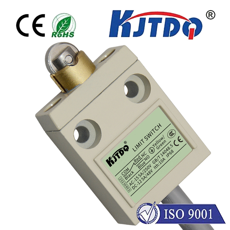
Integrating a limit switch with an Arduino opens up a world of possibilities for precise control in DIY electronics, robotics, and automation projects. A limit switch is a simple electromechanical device that detects the presence or absence of an object, or monitors the movement limits of a mechanism. When combined with the programmability of an Arduino microcontroller, it becomes a powerful tool for creating systems that require accurate positioning, safety cut-offs, or repetitive motion control.
The fundamental operation is straightforward. A typical limit switch has three terminals: common (COM), normally open (NO), and normally closed (NC). In its resting state, the circuit between COM and NO is open, while the circuit between COM and NC is closed. When the switch's actuator (a lever, roller, or plunger) is pressed by an object, these states reverse. For most Arduino interfacing, we use the COM and NO configuration. The COM pin is connected to the Arduino's 5V pin, and the NO pin is connected to a digital input pin on the Arduino, which is also pulled down to ground with a resistor (like a 10kΩ resistor) to ensure a stable LOW signal when the switch is open.
When the switch is not activated, the input pin reads LOW. When an object presses the actuator, the circuit closes, sending 5V to the input pin, which then reads HIGH. The Arduino sketch can continuously monitor this pin's state. For instance, a simple program can be written to stop a motor when the switch is triggered. This is essential in applications like 3D printers or CNC machines, where a moving part must halt precisely at a specific point to prevent damage.
Beyond simple detection, the real power lies in the logic you program. You can use the limit switch as a "home" sensor to initialize a system's position on startup. In a robotic arm project, for example, you can command the arm to move slowly in one direction until it triggers the limit switch. This moment is recorded as the zero or home position, ensuring all subsequent movements are accurate. You can also implement counting mechanisms—each trigger could increment a counter, allowing you to track the number of times a machine cycle completes.
For more complex control, multiple limit switches can be employed. Consider a sliding gate automation system. One switch at the fully open position and another at the fully closed position provide feedback to the Arduino. The program can command a motor to open the gate until the "open" switch is triggered, then stop. To close, it reverses direction until the "closed" switch is triggered. This creates a robust, self-contained control loop. Debouncing the switch input in software is a crucial step to avoid false triggers from mechanical contact vibration, typically achieved by adding a short delay after a state change before reading the pin again.
The wiring is simple, but attention to detail prevents issues. Always ensure the switch is rated for the voltage and current in your circuit. For inductive loads like motors, consider using the Arduino to control a relay module, using the limit switch signal as the control logic. This protects the Arduino's delicate pins. Physically mounting the switch is equally important; it must be positioned so that the moving part reliably activates it without excessive force that could damage the actuator.
In summary, the marriage of a humble limit switch and an Arduino creates a foundation for intelligent control. It transforms a basic on/off sensor into a decision-making component within a programmable ecosystem. From homemade linear actuators and automated curtains to advanced prototyping and industrial simulators, this combination offers reliability, precision, and endless customization through code, empowering makers and engineers to bring their precise motion control ideas to life.