Проверка
Проверка
Проверка
Проверка
Проверка
Проверка
For engineers and maintenance professionals working with industrial machinery, precise control and reliable safety are non-negotiable. The Stromag Limit Switch Series 51 stands as a cornerstone in this domain, offering robust performance for position sensing and travel limitation in demanding applications. This guide delves into the essential information typically found in the Stromag Series 51 manual, providing a clear overview for setup, operation, and troubleshooting, ensuring you can integrate this critical component with confidence.
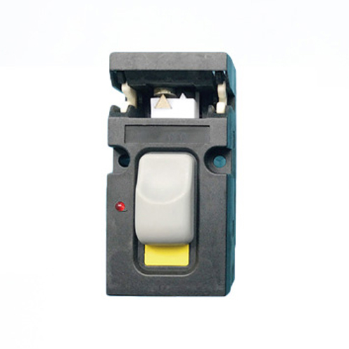
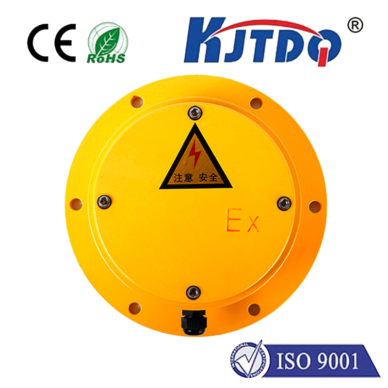
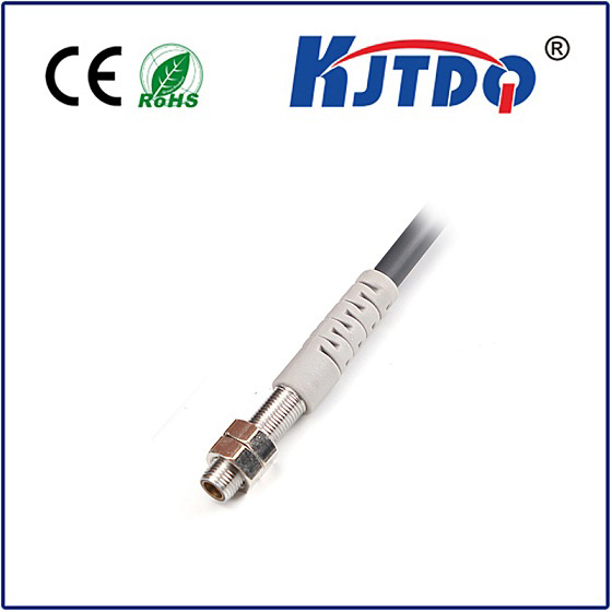
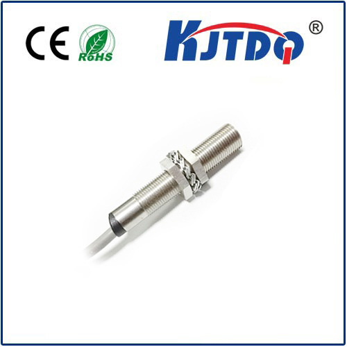
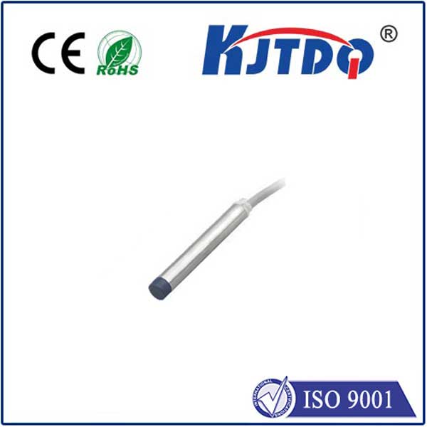
Understanding the Stromag Series 51 begins with its core design philosophy: durability and precision. These limit switches are engineered for harsh industrial environments, featuring a robust housing that offers high resistance to shock, vibration, and contaminants. The series is known for its versatile actuation options, including lever arms with various rollers, cam-operated models, and linear plunger types. This flexibility allows the Series 51 to be adapted to a wide range of mechanical movements, from rotary cranes and conveyor systems to damper controls and material handling equipment. The internal switching mechanism is designed for long electrical life, with clearly marked contacts for easy wiring during installation.
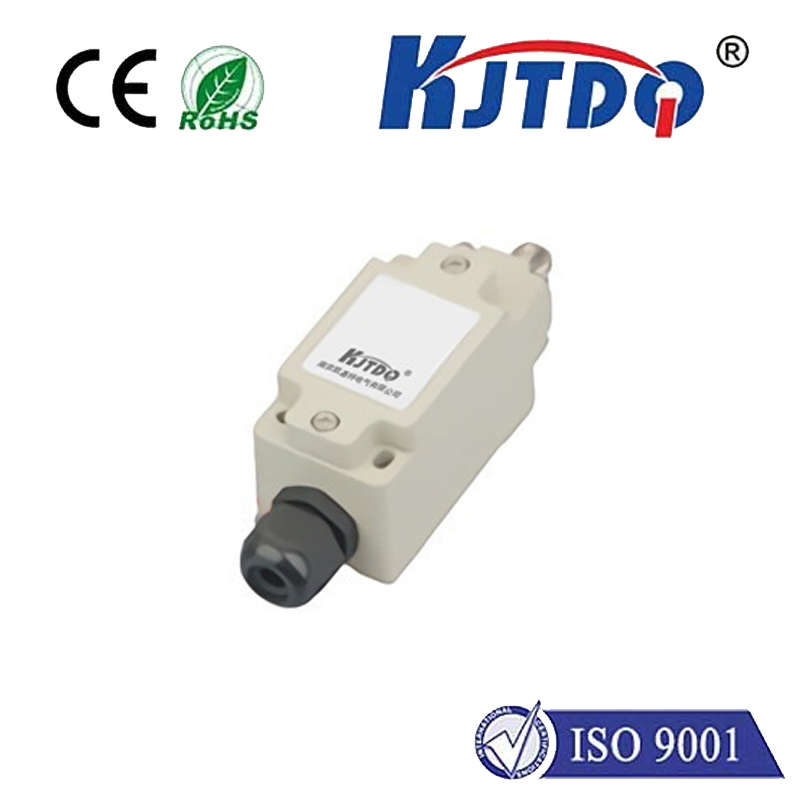
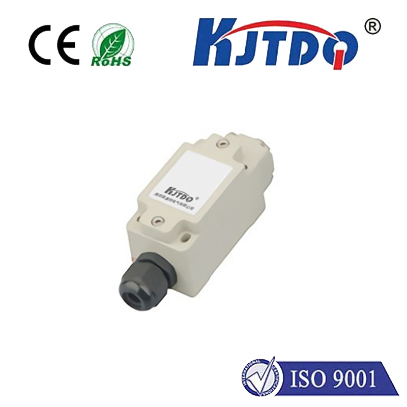
A primary focus of any manual is correct installation, which is paramount for safety and functionality. The first step always involves ensuring the machinery is completely isolated from all power sources—a critical safety precaution. Mounting the switch requires careful alignment. For rotary cam-operated models, the drive unit must be securely fixed, and the cam adjusted to the exact switching points. The mounting position should prevent the ingress of oils or coolants directly onto the switch body. Electrical connection follows the detailed terminal diagram provided. Most Series 51 switches offer both Normally Open (NO) and Normally Closed (NC) contacts. It is vital to use the correct wire gauge and secure cable glands to maintain the unit's ingress protection rating, typically IP65 or higher, which guarantees protection against dust and water jets.
Once installed, adjustment and setting are straightforward but require attention to detail. The setting point is the precise position where the switch actuator triggers a change in the electrical contact state. For lever arm models, the pretravel and overtravel angles must be observed to avoid mechanical overload. Using a simple continuity tester or multimeter is the most reliable way to verify switching during setup. Adjust the actuator or cam position incrementally until the switch triggers exactly at the desired machine position. Many models include adjustable stops or fine-tuning screws for this purpose. Always perform a dry run of the machine cycle at low speed without load to confirm both end limits are correctly sensed before putting the system into full operation.
Routine maintenance is minimal but essential for sustained reliability. Periodically inspect the switch housing for physical damage or cracks. Check that the actuator arm moves freely without binding and that the roller, if present, rotates smoothly. Ensure all electrical connections remain tight, as vibration can loosen terminals over time. The contacts are generally self-cleaning, but in extremely dusty environments, a careful cleaning of the exterior with a dry cloth is recommended. Do not use solvents or high-pressure sprays directly on the unit, as this can compromise seals.
Even with a robust design, occasional issues may arise. A common problem is the switch failing to actuate. This is often traced to mechanical misalignment, a bent actuator arm, or worn roller. Re-alignment or part replacement is necessary. If the switch actuates but the control signal is absent, the issue is likely electrical. Verify power supply, check for loose wires at the terminals, and test contact continuity with the actuator manually operated. Persistent electrical failure may indicate internal contact wear, necessitating unit replacement. Remember, never bypass a safety limit switch as a temporary fix; this poses a severe safety risk to personnel and equipment.
The Stromag Limit Switch Series 51 embodies a legacy of German engineering precision, providing a critical interface between mechanical movement and electrical control systems. Its comprehensive manual serves as a blueprint for unlocking this reliability. By following the fundamental principles of safe installation, precise adjustment, and proactive maintenance outlined here, you ensure that this component performs its vital role effectively for years to come, safeguarding your processes and productivity.