Проверка
Проверка
Проверка
Проверка
Проверка
Проверка
For CNC enthusiasts and professionals, the persistent clicking, buzzing, or chattering sound from GRBL limit switches is a common and often frustrating issue. This noise, far from being a mere annoyance, can signal underlying problems that may affect machine accuracy, reliability, and even safety. Understanding the root causes of GRBL limit switch noise and implementing effective solutions is crucial for maintaining a smooth and precise operation.
The primary culprit behind limit switch noise in a GRBL-controlled system is electrical interference, commonly known as noise or electrical noise. GRBL limit switches are typically simple mechanical or proximity sensors that send a signal to the Arduino-based controller when triggered. The long wires running from these switches to the control board act as perfect antennas, picking up electromagnetic interference (EMI) from various sources. Stepper motor drivers, especially when using high microstepping settings or during rapid direction changes, are significant generators of EMI. Spindle motors, VFDs, and even other nearby machinery can contribute to this electrical soup. This interference can induce false voltage spikes on the signal lines, causing the GRBL controller to erratically detect a limit switch trigger, resulting in audible clicks from the control board or erratic machine behavior.
Another frequent cause is switch bounce. Mechanical limit switches have physical contacts that, when closed, can vibrate or "bounce" for a few milliseconds before settling. To GRBL's fast-processing microcontroller, this bounce can appear as multiple rapid triggers. While GRBL has software debounce filtering (configurable via the$27 setting), it may not be sufficient for particularly bouncy switches or environments with high electrical noise, leading to audible chatter from the driver or relay circuits.
Poor wiring practices exacerbate both issues. Running signal wires parallel and close to motor power cables creates capacitive coupling, allowing noise to transfer easily. Loose connections, frayed wires, or inadequate grounding provide unstable paths that are more susceptible to interference. Using unshielded cables for limit switch circuits is an open invitation for noise.
Fortunately, a systematic approach can effectively silence your machine. The first and most impactful step is implementing proper wiring techniques. Always use shielded cable for all limit switch connections. Connect the shield drain wire to a single-point ground at the controller end only, typically the Arduino's ground. This shield acts as a Faraday cage, blocking external EMI. Crucially, route these signal cables away from motor power cables and spindle wiring. If they must cross, ensure they do so at a 90-degree angle to minimize coupling. Keep wires as short as practically possible and secure all connections firmly.
At the switch end, adding a hardware debounce circuit can work wonders, especially for mechanical switches. A simple resistor-capacitor (RC) filter across the switch terminals can smooth out the bounce. A common configuration is to use a 0.1µF ceramic capacitor connected directly across the switch contacts. For a more robust solution, especially in noisy environments, consider using opto-isolated limit switches or adding external opto-isolator modules. These devices use light to transmit the signal, creating a complete electrical barrier between the noisy machine side and the sensitive controller side, virtually eliminating conducted noise.
On the controller side, ensure you are using a quality, regulated power supply for both the Arduino and the stepper drivers. Voltage fluctuations can induce noise. You can also add small capacitors (e.g., 0.1µF) between the signal input pins and ground on the Arduino board itself to filter high-frequency noise at the entry point. Fine-tuning GRBL's debounce setting ($27) is essential. Increase this value in small increments (the value is in milliseconds) until the false triggers stop. Start with a setting like 25 (ms) and adjust as needed.
For persistent noise issues, reconfiguring the limit pins to use the Arduino's internal pull-up resistors (if not already active) can provide a cleaner, more stable signal reference. In GRBL, this is usually the default. Verify your switch wiring is correct for a normally-open (NO) configuration, which is standard and less prone to certain failure modes that can cause noise.
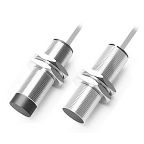
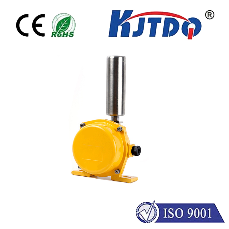
Finally, consider the switch type itself. High-quality, sealed mechanical switches or solid-state proximity sensors (inductive or capacitive) are often more resistant to environmental contaminants and can offer cleaner signals. Ensure any proximity sensor is correctly rated for your voltage and is properly shielded.
By methodically addressing wiring, adding hardware filtration, and optimizing software settings, you can effectively eliminate GRBL limit switch noise. The result is not just a quieter workshop but a more reliable, accurate, and safer CNC machine that responds predictably to genuine limit commands, protecting your workpiece and equipment from potential damage due to false triggers.