Проверка
Проверка
Проверка
Проверка
Проверка
Проверка
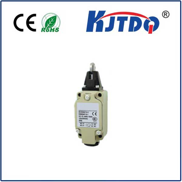
In industrial automation and control systems, actuator limit switches play a critical role in ensuring safe, precise, and reliable operation of mechanical components. Understanding the actuator limit switch schematic is fundamental for engineers, technicians, and maintenance personnel involved in system design, installation, and troubleshooting. This guide delves into the core principles, typical wiring configurations, and practical considerations for interpreting and implementing these essential schematics.
At its heart, an actuator limit switch is a sensor mounted on a linear or rotary actuator. Its primary function is to detect the physical position of the actuator's moving part—typically the piston rod in a pneumatic or hydraulic cylinder or the shaft of an electric actuator. When the actuator reaches a predefined endpoint (fully extended or fully retracted), it mechanically triggers the limit switch. This action changes the switch's electrical state, sending a signal back to the control system, such as a Programmable Logic Controller (PLC). This signal is crucial for logic sequences, preventing over-travel, initiating the next step in a process, or providing safety interlocks.
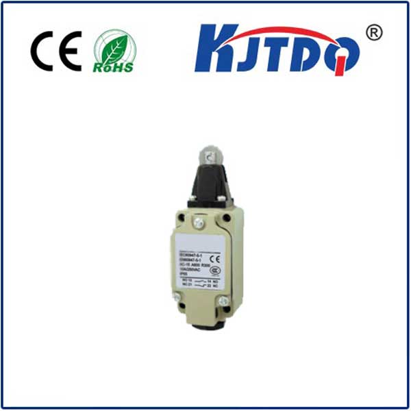
A standard actuator limit switch schematic symbol represents a switch with normally open (NO) and/or normally closed (NC) contacts. The schematic does not usually depict the physical actuator; instead, it focuses on the electrical circuit of the switch itself. You will typically see the switch contacts connected to a terminal block or directly to the control device. A common schematic shows a simple two-wire connection: one wire from a power source (often 24V DC) to one terminal of the switch contact, and the other wire from the second terminal of the switch to the input module of the PLC. When the actuator triggers the switch, the contact closes (for an NO configuration), completing the circuit and allowing current to flow to the PLC input, which the PLC program interprets as a "limit reached" signal.
For more complex control, especially for monitoring both extend and retract positions, a schematic will include two separate limit switches—one for each end of travel. These are often labeled as "LS1" (Limit Switch 1) for the retracted position and "LS2" (Limit Switch 2) for the extended position. Their contacts are wired to discrete inputs on the PLC. The control logic within the PLC ladder diagram or function block diagram uses these inputs to permit or halt actuator movement. For instance, the "extend" output coil in the PLC program might be energized only if the "retracted limit switch" (LS1) signal is ON and the "extended limit switch" (LS2) signal is OFF.
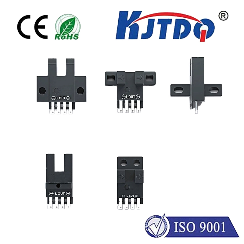
Beyond basic two-wire setups, schematics may incorporate three-wire configurations with NAMUR-type proximity sensors or solid-state switches, which require a separate power supply. These schematics clearly show the positive supply, negative/ground, and signal output wires. Furthermore, safety-rated limit switches used in critical applications will have redundant contacts (e.g., two NC contacts in series) wired to a safety relay, a detail explicitly shown in their schematics to ensure fail-safe operation.
When reading an actuator limit switch schematic, pay close attention to several key details. First, identify the contact state (NO or NC) as drawn. This is paramount, as misinterpreting this can lead to dangerous control logic errors. Second, note the voltage and current ratings indicated on the schematic to ensure compatible power supplies and loads. Third, trace the wire numbering or labeling; this correlates directly with the physical wiring on the terminal strips and is invaluable for debugging. Finally, understand the associated PLC input address (e.g., I0.1) noted next to the wire; this links the physical hardware to the software logic.
Practical application of these schematics is widespread. In a packaging machine, limit switches on a sealing cylinder confirm the clamp is closed before the heat cycle begins. In a material handling system, they ensure a robotic gripper is fully home before a conveyor starts. A faulty or misaligned limit switch, evident when the schematic's expected electrical state doesn't match a multimeter's reading at the terminals, can cause machine faults, production stoppages, or even equipment damage.
Successful implementation starts with selecting the right switch—mechanical lever arm, proximity, or reed—based on environmental factors like dust, moisture, and vibration. During installation, precise mechanical alignment with the actuator's cam or flag is essential for consistent triggering. The schematic is the roadmap for correct electrical connection, but the physical mounting is equally important. Regular maintenance, including checking for loose wires, contact corrosion, and mechanical wear, ensures the real-world system continues to match the reliability designed into the schematic.
In conclusion, the actuator limit switch schematic is more than just a drawing; it is the foundational document that translates mechanical position into actionable electrical intelligence. Mastery of its symbols, conventions, and wiring practices is essential for building and maintaining robust automated systems. By correctly interpreting and applying the schematic, professionals guarantee that actuators operate within their intended boundaries, enhancing both the safety and efficiency of industrial operations.