Photoelectric sensor circuits form the backbone of modern automation, enabling non-contact detection of objects, colors, and distances. These systems convert light signals into electrical currents, providing reliable data for industrial controls, safety systems, and consumer electronics. Understanding their core components and operational principles is essential for engineers and hobbyists alike.
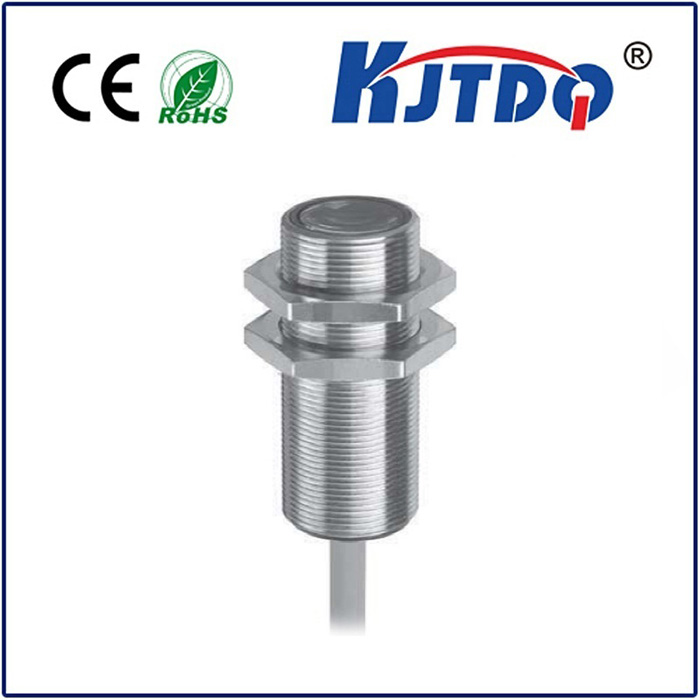
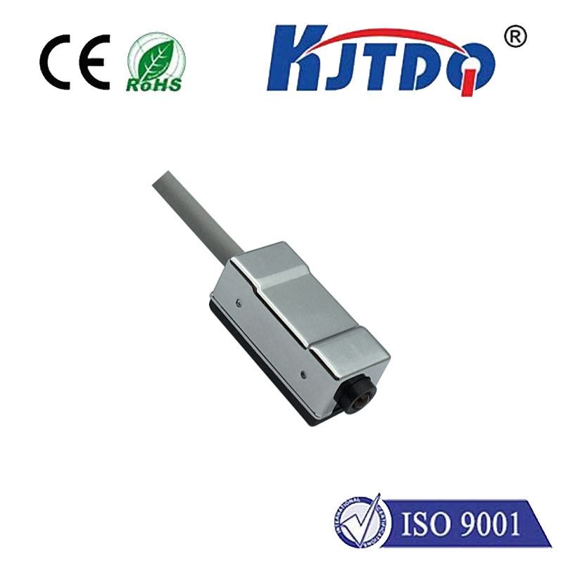
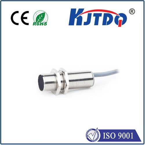
A basic photoelectric sensor circuit consists of three key elements: an emitter, a receiver, and signal processing electronics. The emitter, typically an LED or laser diode, projects a beam of light. The receiver, a phototransistor or photodiode, detects changes in this light beam. When an object interrupts or reflects the light, the receiver generates a corresponding electrical signal. This raw signal is then amplified, filtered, and shaped by the processing circuit into a clean, digital output usable by microcontrollers or PLCs.
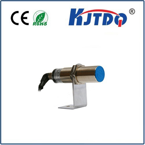
Several circuit configurations exist, each suited for specific applications. The most common is the opposed (through-beam) mode, where the emitter and receiver face each other. This setup offers the longest sensing range and highest reliability, ideal for detecting opaque objects on conveyor belts. The retro-reflective mode uses a single unit housing both emitter and receiver, along with a reflector. It's a cost-effective solution for medium-range detection. Finally, the diffuse (proximity) mode relies on light reflected directly from the target object. While sensitive to object color and surface texture, it's perfect for short-range applications and detecting non-reflective materials.
Designing a robust circuit requires careful component selection. For the emitter, infrared LEDs are popular due to their high output and immunity to ambient light interference, but visible red or laser diodes are chosen for precise alignment. Phototransistors provide high sensitivity and built-in amplification, whereas photodiodes offer faster response times crucial for high-speed counting. The operational amplifier (op-amp) circuit is critical for conditioning the weak receiver signal. A transimpedance amplifier configuration is standard, converting the photodiode's current output into a stable voltage. Designers must also incorporate ambient light rejection techniques, such as modulating the emitter light at a specific frequency and tuning the receiver circuit to that same frequency, effectively filtering out background noise.
Power supply stability is non-negotiable. Voltage fluctuations directly affect the emitter's light intensity and the receiver's sensitivity, leading to false triggers. Implementing proper voltage regulation and decoupling capacitors near the active components is a fundamental best practice. Furthermore, for circuits driving inductive loads like relays, protection diodes are mandatory to prevent voltage spikes from damaging sensitive semiconductors.
The real-world applications are vast. In manufacturing, these circuits count bottles, detect label positions, and ensure product placement. In automotive assembly, they verify part presence. Security systems use them for door and gate monitoring. Even everyday devices like printers and automatic faucets rely on these silent sentinels. A well-designed photoelectric sensor circuit provides a perfect blend of reliability, speed, and cost-effectiveness, making it an indispensable tool in the engineer's toolkit. Successful implementation hinges on a clear understanding of the sensing environment, object properties, and the electrical noise landscape.