Проверка
Проверка
Проверка
Проверка
Проверка
Проверка
Imagine a critical moment on a high-speed packaging line. A tiny, crucial component fails to arrive at the precise spot for assembly. The machine hesitates, searching, costing precious seconds and risking costly downtime. Often, the unsung hero preventing – or, if chosen poorly, causing – such chaos is a photoelectric sensor. Specifically, understanding the interplay between photoelectric sensing principles, ПНП vs. НС outputs, and the unique capabilities of fiber optic sensors is key to unlocking reliable and efficient automation. This guide cuts through the complexity, empowering you to select the right sensor configuration for your toughest applications.
The Core of Photoelectric Sensing
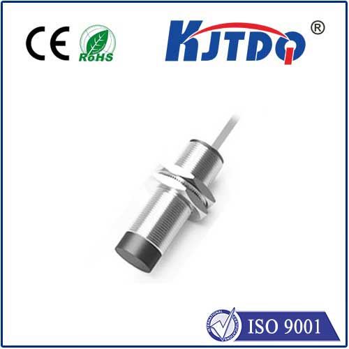
At its heart, a photoelectric sensor operates on a simple yet powerful principle: it uses light to detect the presence, absence, or distance of an object. An emitter sends out a beam of light (visible, infrared, or laser), and a receiver monitors this light. When the beam is interrupted, reflected, or modulated by a target object, the sensor’s internal circuitry triggers a change in its выходной сигнал. This fundamental technology excels in non-contact detection across countless industries, offering speed, reliability, and versatility beyond mechanical switches. Whether confirming part presence, counting items, detecting fill levels, or ensuring safety barriers, Фотоэлектрический датчик are automation workhorses.
Enter Fiber Optics: Extending the Reach
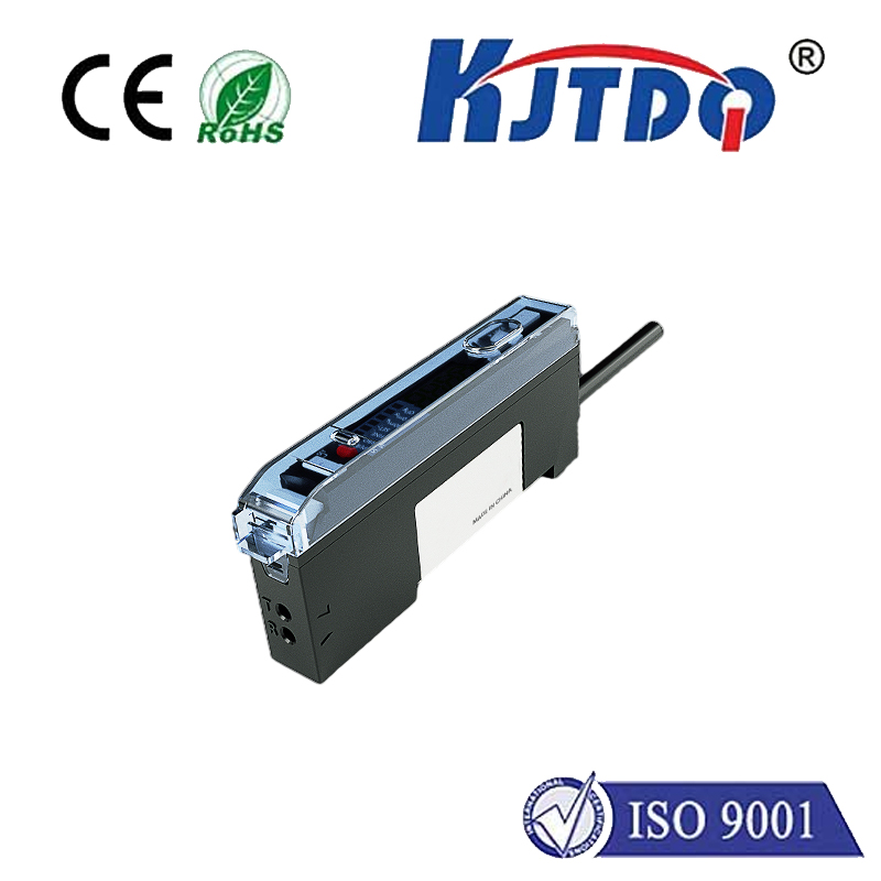
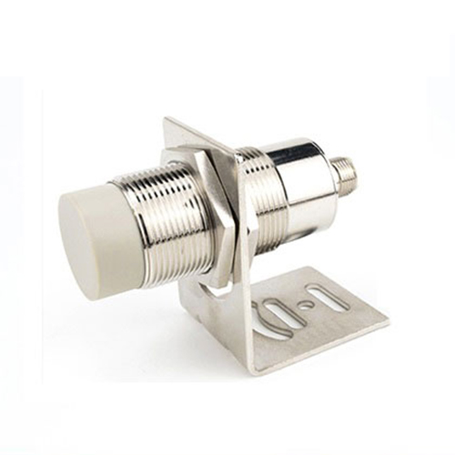
While traditional photoelectric sensors house both emitter and receiver in a single unit, fiber optic sensors bring a unique twist. They utilize flexible light conduits – optical fibers – to separate the sensing point from the sensor’s electronics. The emitter’s light travels down one fiber strand to the sensing head. Depending on the sensor type (through-beam, retro-reflective, diffuse), the light interacts with the target and either travels back through a separate receiver fiber or is blocked. The separated electronics housing contains the light source, detector, and output circuitry.
This separation unlocks critical advantages:
The Critical Choice: PNP vs. NPN Outputs

Here’s where the terms ПНП and НС become decisive. They refer to the Тип of transistor switch used in the sensor’s output stage. This defines how the sensor connects to your controller (PLC, counter, robot) and the electrical behavior of its signal. Understanding this difference is non-negotiable for correct system integration and avoiding potential damage.
PNP (Sourcing) Output: Think “Positive Switching.” When the sensor is active (detects the target, depending on configuration), its output line sources or supplies positive voltage (typically +24V DC) from the sensor to the load (your PLC input point). The load is connected between the sensor’s output wire and the system’s 0V (common / ground). In essence, a PNP sensor acts like a switch connecting the load to +V when active.
Common Region Use: Predominantly used in Europe and Asia.
NPN (Sinking) Output: Think “Negative Switching” or “Sinking to Ground.” When the sensor is active, its output line connects the load to 0V (ground). The load must be connected between the system’s positive voltage (+24V DC) and the sensor’s output wire. An NPN sensor acts like a switch connecting the load to ground (0V) when active.
Common Region Use: Predominantly used in North America and Japan.
Choosing Between PNP and NPN for Your Fiber Optic Sensor
Selecting the right output type isn’t about inherent superiority; it’s about matching the sensor to your control system’s input requirements.
Why PNP/NPN Matters Most with Fiber Optics?
While the Фотоэлектрический датчик principle is core, and the fiber optic sensor construction solves physical challenges, the ПНП or НС output determines the electrical language the sensor speaks to your controller. A perfectly detecting fiber optic head is useless if its output signal is incompatible with the system it needs to communicate with. Getting the PNP/NPN selection wrong is one of the most common installation errors.
Key Advantages of Fiber Optic Photoelectric Sensors
Combining photoelectric reliability with fiber flexibility yields a powerful solution:
Selecting the Right Tool for the Job
Choosing the optimal fiber optic sensor involves several steps: