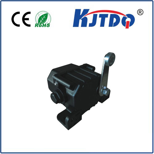
ограничительный выключатель тележки
- time:2025-08-07 01:40:58
- Нажмите:0
Trolley Limit Switch: The Unsung Guardian in Overhead Crane Safety
Imagine this: a heavy load suspended from an overhead crane, gliding smoothly along the runway beam. Suddenly, the operator loses focus, or a control signal malfunctions. Without a crucial safeguard, that trolley carrying tons of material could overshoot its path, hurtling towards the end of the beam with catastrophic potential – collision, structural damage, or even worse, injury. This is where the unassuming yet utterly critical trolley limit switch steps in, acting as the final line of defense. Understanding how this component works and why it’s indispensable is vital for anyone involved in material handling safety and efficiency.
What Exactly is a Trolley Limit Switch?
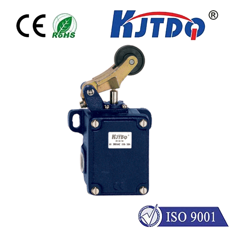
At its core, a trolley limit switch is a precision-engineered safety device integrated into overhead crane trolleys and runway systems. Its primary function is to automatically halt the trolley’s travel before it reaches the physical end of its permitted path along the bridge girder or runway. It’s a type of position sensor designed to detect the trolley’s approach to a predetermined travel boundary and immediately interrupt the power supply to the trolley’s travel motor. This controlled stop prevents the trolley from crashing into end stops, derailing, or causing damage to the crane structure, building infrastructure, or surrounding equipment. Essentially, it defines the operating envelope for the trolley’s movement.
The Vital Role in Crane Safety and Operational Control
The importance of trolley limit switches cannot be overstated. They are fundamental to:

- Collision Prevention: The most obvious function – stopping collisions between the trolley and physical end stops or adjacent structures, averting costly damage and potential structural compromise.
- Operator and Personnel Safety: By preventing runaway trolleys and uncontrolled impacts, these switches directly mitigate risks of injury to crane operators and nearby workers. They are a cornerstone of any compliant safety program.
- Equipment Protection: Preventing violent impacts protects not only the trolley wheels and end stops but also the entire crane bridge structure, runway beams, and the motors/gearboxes driving the trolley from excessive shock loads.
- Process Integrity: In automated or semi-automated systems, limit switches provide precise positional control, ensuring the trolley stops accurately at designated pickup or setdown points, crucial for smooth workflow.
- Regulatory Compliance: Adherence to safety standards like OSHA (Occupational Safety and Health Administration) in the US, CMAA (Crane Manufacturers Association of America), FEM (European Materials Handling Federation), and others mandates the installation and proper functioning of trolley travel limit switches as essential safety features. Failure to comply can lead to hefty fines and shut-down orders.
How Does a Trolley Limit Switch Operate?
The operation is elegantly straightforward, relying on physical actuation:
- Positioning: The switch unit itself is typically mounted in a fixed location near each end of the trolley’s travel path on the crane bridge or runway structure.
- Actuator Engagement: An actuator arm, roller lever, rod, or cam – physically attached to the moving trolley – is positioned to make contact with the fixed switch.
- Contact Trigger: As the trolley approaches its limit, the moving actuator engages the stationary limit switch mechanism. This physical engagement is key.
- Circuit Interruption: Upon actuation, the switch’s internal contacts change state (open or close, depending on design). This action sends a signal to the crane’s motor control center (MCC) or drive controller.
- Motor Cut-off: The controller interprets this signal as a command to immediately cut power to the trolley’s travel motor(s), initiating a controlled stop (often using braking systems).
- Reset: Once the trolley direction is reversed (away from the limit), the actuator disengages, the switch contacts return to their normal position, and power to the travel motor in the safe direction is restored.
Types of Trolley Limit Switches: Choosing the Right Guardian
Several designs exist, suited to different environments and operational needs:
- Lever Arm Limit Switches: Feature a hinged arm with a roller. Contact is made when the trolley-mounted actuator trips the lever. Highly versatile and common. Ideal for slower speeds and moderate accuracy.
- Rotary Cam Limit Switches: Utilize a rotating camshaft driven by the trolley’s movement (often via a cable or chain). Cams on the shaft open/close contacts at precise rotational positions. Offer excellent repeatability and accuracy for multiple control points or slow creep speeds near limits. Essential for applications requiring precise positioning.
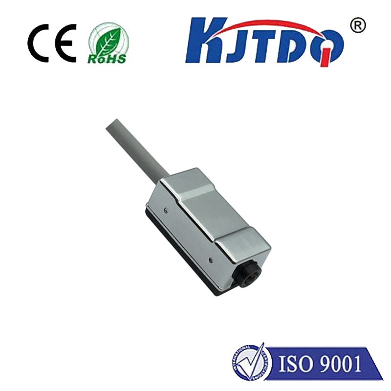
- Rod-Type Limit Switches: Employ a spring-loaded plunger or rod. Contact occurs when the plunger is depressed by the trolley’s actuator. Simple and robust. Suitable for harsh environments where levers might get snagged.
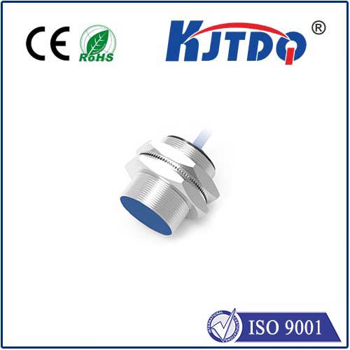
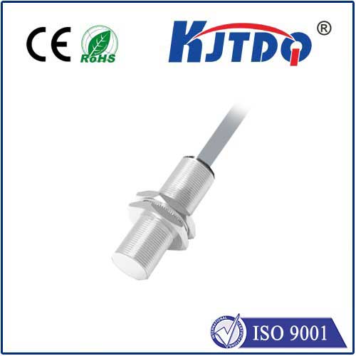
- Proximity Sensors (Magnetic/Inductive): While not strictly mechanical “switches,” non-contact sensors are increasingly used. They detect the presence of a metal target on the trolley without physical touch, offering high reliability and resistance to dirt/contaminants. Excellent for environments demanding minimal maintenance.
Key Considerations for Selection and Installation
Choosing and installing the right trolley limit switch is paramount for reliable performance:
- Environment: Is the crane indoors or outdoors? Exposure to dust, moisture, chemicals, or extreme temperatures dictates the required NEMA/IP rating (e.g., NEMA 4, 4X, 6P, IP65, IP67).
- Duty Cycle: How frequently will the switch be actuated? Heavy-duty cycles demand robust contacts and mechanisms.
- Trolley Speed and Weight: Higher speeds and heavier loads require switches designed to handle the associated kinetic energy and potential shock during stopping.
- Actuation Force & Repeatability: Ensure the actuator mechanism provides sufficient force to reliably trip the switch consistently, even under vibration.
- Mounting Location & Actuator Design: Position switches where they are accessible for adjustment and inspection but protected from accidental damage. The actuator must engage the switch reliably throughout the trolley’s life (considering wheel wear).
- Fail-Safe Positioning: Switches should be installed so that failure (e.g., broken spring, damaged linkage) defaults to the safe state (usually cutting power to the motor).
- Adjustability: Fine-tuning the exact stopping point is crucial. Switches should allow for precise setting of the actuation point during installation and commissioning.
Maintenance: Ensuring Your Guardian Remains Vigilant
Like all safety components, trolley limit switches require regular attention:
- Visual Inspections: Regularly check for physical damage, corrosion, loose mounting, or damaged actuator components. Look for signs of impact.
- Operational Testing: Periodically (as per safety protocols, often daily or weekly checks) manually trip the switch (using a non-conductive tool if possible) while the trolley is moving slowly towards the limit. Verify the trolley stops as expected before reaching the mechanical end stop. This is non-negotiable for safety compliance.
- Contact Check & Cleaning: For mechanical switches, inspect contacts for wear, pitting, or contamination. Clean contacts per manufacturer guidelines using appropriate contact cleaner and tools. Check terminal tightness.
- Actuator Alignment: Ensure the actuator reliably engages the switch without binding or excessive force. Adjust if necessary.
- Replacement: Replace switches showing significant wear, damage, or inconsistent operation immediately. Never bypass a faulty limit switch!
The trolley limit switch is far more than a simple component; it is an active, vigilant **safety sent