Ограничительный переключатель маршрутизатора cnc
- time:2025-08-04 12:14:55
- Нажмите:0
CNC Router Limit Switches: Your Machine’s Unsung Safety Guardians
Think of your CNC router carving intricate designs, zipping along its axes with precision. Now, imagine that same head or gantry just keeps going, slamming into the frame or trying to push past its physical boundaries. The potential for catastrophic damage – snapped drive screws, bent rails, destroyed motors – is terrifyingly real. This nightmare scenario is precisely what CNC router limit switches are designed to prevent. Far from being minor accessories, these often-overlooked components are critical safety mechanisms, acting as the final line of defense against costly machine crashes and ensuring operational integrity.
What Exactly Are Limit Switches?
In essence, CNC router limit switches are sensor devices strategically placed at the physical extremities of each axis (X, Y, and Z) of your machine. Their job is brutally simple: to detect when an axis has reached its predefined maximum travel limit. When the moving part (like the gantry or spindle carriage) contacts a switch’s actuator, it triggers an immediate signal to the machine’s controller.
This signal forces the machine into an emergency stop state. All motion ceases instantly, preventing any further travel in that direction. Think of them like the bumpers at the end of a bowling lane. Their core function is overtravel protection. Without them, a software glitch, programming error, motor malfunction, or homing failure could easily lead to destructive physical impacts.
Why Ignoring Limit Switches is a Costly Mistake
The value of functional limit switches becomes starkly clear when considering the consequences of their absence or failure:

- Mechanical Carnage: The most obvious risk. Direct impacts can bend linear rails, damage ball screws or rack-and-pinion systems, crack machine frames, destroy motor couplings, and shatter spindle components. Repairs are expensive and cause significant downtime.
- Motor and Drive Damage: Motors forced to stall against a hard stop can overheat, burn out windings, or destroy associated servo drives or stepper drivers, especially if the controller doesn’t detect the stall quickly enough. High torque at the moment of impact can also shear mechanical components.
- Safety Hazard: While primarily protecting the machine, limit switches also contribute indirectly to operator safety. A runaway axis or gantry poses a physical danger to anyone nearby. A sudden, violent crash can also dislodge workpieces or tooling unpredictably.
- Extended Downtime: Replacing damaged components takes time. Sourcing parts, performing repairs, and recalibrating the machine can halt production for hours or days. Lost production time translates directly to lost revenue.
Homing: The Vital Starting Point
Limit switches play a second, equally crucial role beyond emergency stops: they are fundamental to the homing procedure. Homing is the process a CNC router performs (usually at startup or after an E-stop) to determine its absolute zero position within its mechanical travel.
By physically moving each axis until it triggers its respective limit switch, the controller establishes a known, repeatable reference point. Only after accurately homing can the machine correctly execute programs relative to the machine’s coordinate system. Reliable limit switches are absolutely essential for accurate and repeatable homing. Poorly adjusted, faulty, or inconsistent switches will lead to homing errors, incorrect positioning, and potentially crashes later in the job if the machine “thinks” it has more travel than it actually does.
Тип ограничительного переключателя
CNC routers typically utilize a few common types of limit switches, each with pros and cons:
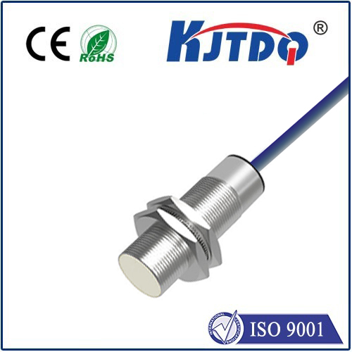
- Mechanical Microswitches:
- How They Work: Feature a physical lever or roller plunger. When the moving machine part contacts the lever/roller, it physically activates the switch internally.
- Pros: Simple, robust, reliable, cost-effective, easy to replace. Can handle some environmental debris.
- Cons: Physical contact means eventual mechanical wear. Can be susceptible to vibration or impact damage over time. Sensitive to physical misalignment.
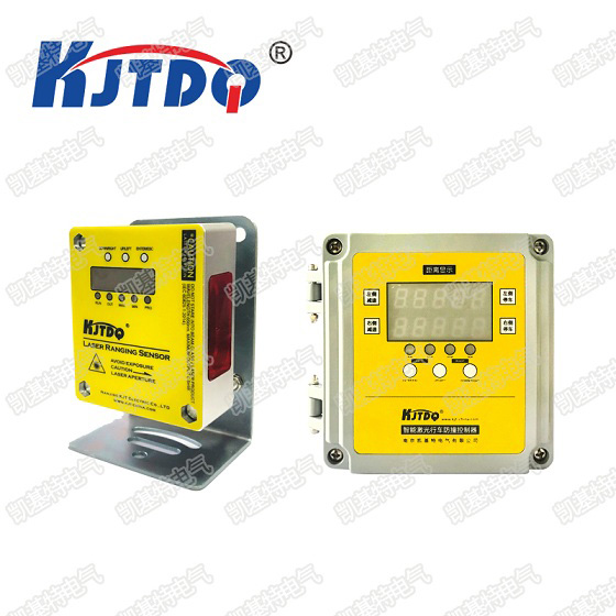
- Optical (Photoelectric) Switches:
- How They Work: Use an infrared light beam emitted by one unit (emitter) and detected by another (receiver), or a reflector system. When an axis flag interrupts the light beam, the switch triggers.
- Pros: Non-contact operation means no physical wear on the switch itself. Very fast response time. Highly reliable when clean. Excellent repeatability.
- Cons: Sensitive to dust, wood chips, coolant mist, and other debris blocking the beam. Require precise alignment. Often more expensive than mechanical switches.
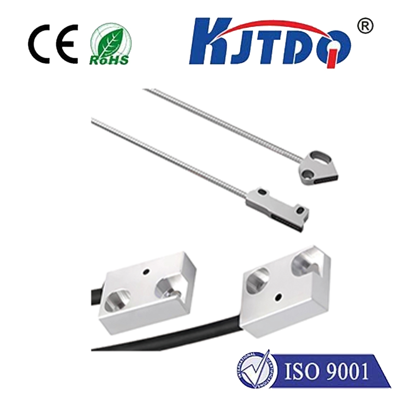
- Magnetic (Reed or Hall Effect) Switches:
- How They Work: Activate when a magnet mounted on the moving axis comes into close proximity to the stationary sensor.
- Pros: Non-contact, wear-free operation. Excellent resistance to dust and debris (as long as the magnet surface is somewhat clean). Highly reliable and long-lasting. Good resistance to vibration. Simple installation.
- Cons: Magnetic field strength and sensor sensitivity require careful setup. Strong external magnetic fields could potentially cause interference (rare in typical CNC environments). Cost can be higher than mechanical.
Best Practices: Installation, Maintenance, and Troubleshooting
Ensuring your limit switches perform flawlessly requires attention:
- Strategic Placement: Position switches where they can be reliably triggered by a dedicated flag or part of the gantry/carriage before any mechanical collision occurs. Consider accessibility for maintenance.
- Robust Mounting: Securely fasten both the switch and the actuator flag. Vibration loosening screws is a common failure point. Use lock washers or thread-locker.
- Debris Management: Especially critical for optical switches. Use shrouds, air blasts, or frequent cleaning to keep beam paths clear. Keep magnet surfaces clean on magnetic types.
- Regular Inspection: Make switch checks part of routine preventative maintenance. Verify physical integrity (no broken levers/casings), mounting security, and cleanliness. Test functionality periodically by manually triggering each switch during a controlled test (e.g., slow jog towards the limit).
- Calibration: After installation or adjustment, ensure the machine accurately homes and recognizes the limit trigger point. Software settings (like soft limits) often rely on the precise position found after hitting the hard limit switch.
- Wiring Integrity: Protect cables from snagging, abrasion, and dust. Loose or corroded connections are a frequent source of intermittent switch failure. Ensure ground connections are solid to prevent electrical noise issues.
- Troubleshooting Common Issues: If you encounter strange homing failures, unexpected E-stops, or the machine ignores a limit, check:
- Is the switch physically triggered? (Look for alignment issues, bent levers, obstructed flags)
- Is the wiring intact? (Check connections, continuity)
- Is the switch clean and debris-free? (Especially optical sensors/emitters)
- Is the magnet still securely attached and positioned correctly? (Magnetic types)
- Has the switch itself failed? (Test with a multimeter or try swapping with a known-good switch). Diagnosing a faulty switch is often simpler than chasing controller errors.
Beyond the Basics: Soft Limits and Dual Homing
Most modern CNC controllers implement soft limits – programmable boundaries slightly inside the physical limit switch positions. Once the machine is homed and knows its exact travel range, the controller software prevents movement beyond the soft limits, acting as a proactive safeguard. However, soft limits rely entirely on the machine knowing its true position. If homing fails or position is lost (e.g., after an E-stop), soft limits become ineffective. This is why the physical limit switches are the essential, non-negotiable, fail-safe layer.
Some advanced systems use two switches per axis: one for the home position and one at the extreme limit. This provides even greater precision for homing and redundancy for overtravel protection.
Never underestimate the importance of these unassuming components mounted at the edges of your CNC router’s travel. **