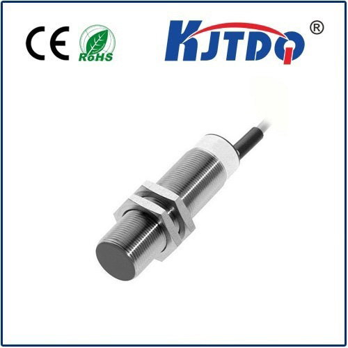
(Intro Hook) That satisfying “click” as an elevator door closes without touching you, the precise stopping point of a high-speed CNC machine, or the automated counting of cans rushing down a factory line – the unseen heroes behind these moments are often индукционный датчик. Harnessing the power of electromagnetic fields, these robust, contactless devices excel at detecting metal objects reliably, even in harsh environments filled with dust, oil, or vibration. For makers, engineers, and automation enthusiasts, pairing inductive sensors with Arduino unlocks a world of possibilities for adding industrial-grade proximity sensing to your DIY projects or professional prototypes. This guide dives deep into the why and how.
Why Choose Inductive Sensors with Arduino?
Inductive sensors operate on a fundamental principle: electromagnetic induction. Inside the sensor’s head lies a coil energized with high-frequency alternating current. This creates an oscillating electromagnetic field. When a metallic object enters this detection field, it induces small electrical currents (eddy currents) within the metal. These eddy currents draw energy from the sensor’s coil, causing a measurable change in the oscillation amplitude or frequency.
Arduino compatibility arises from the sensor’s output stage. Most modern inductive sensors designed for industrial control offer simple transistor outputs (NPN or PNP):
These digital (on/off) or analog signals are perfectly readable by an Arduino’s digital or analog input pins, making integration remarkably straightforward. Key advantages include:

Getting Connected: Wiring Up Your Inductive Sensor
Connecting an inductive sensor to your Arduino involves a few crucial steps:
*(Crucial Note on Power & Grounding):* Proper power and a common ground connection between the sensor’s power supply and the Arduino are non-negotiable for reliable operation. Double-check before powering on!
Reading the Sensor: Arduino Code Essentials
Reading a digital inductive sensor is incredibly simple. Use the digitalRead() function on the connected pin.
// Define pin connected to sensor output (NPN NO sensor wiring example)
#define INDUCTIVE_SENSOR_PIN 2
void setup() {
Serial.begin(9600);       // Start serial communication
pinMode(INDUCTIVE_SENSOR_PIN, INPUT); // Set pin as input
}
void loop() {
int sensorState = digitalRead(INDUCTIVE_SENSOR_PIN); // Read the pin
if (sensorState == LOW) { // Assuming NPN NO: LOW when target detected
Serial.println("Metal Object Detected!");
// Add your action here (turn on LED, activate relay, etc.)
} else {
Serial.println("No Detection");
// Optional: Add action when target is absent
}
delay(100); // Short delay for readability/simulation
}
For analog inductive sensors (providing distance-proportional voltage):
#define ANALOG_SENSOR_PIN A0
void setup() {
Serial.begin(9600);
// Analog pins are inputs by default
}
void loop() {
int sensorValue = analogRead(ANALOG_SENSOR_PIN); // Read 0-1023
float voltage = sensorValue * (5.0 / 1023.0);    // Convert to volts (if Arduino 5V)
float distance = map(sensorValue, minADC, maxADC, maxDist, minDist); // *Calibrate!*
Serial.print("Raw: ");
Serial.print(sensorValue);
Serial.print(", Voltage: ");
Serial.print(voltage);
Serial.println("V");
// Use voltage or calculated distance for control logic
delay(100);
}
Important: Calibrate analog sensors! Determine the minimum (minADC) and maximum (maxADC) values your sensor outputs at the relevant distances (minDist, maxDist) and use map() accordingly or calculate using the sensor’s datasheet specs.
Putting It Into Action: Project Ideas
The combination of inductive sensors and Arduino opens doors to numerous applications:
