Сеть датчиков приближения
- time:2025-06-24 01:21:46
- Нажмите:0
The Silent Guardian: Demystifying Proximity Sensor Circuits for Seamless Detection
Ever brushed your hand near a faucet, and water magically flowed? Or approached a store entrance, triggering the automatic doors? This unseen intelligence, reacting to your presence without contact, is the remarkable work of proximity sensors. But the real magic lies not just in the sensor element itself, but in the intricate electronic heartbeat behind it: the proximity sensor circuit. This rangkaian transforms raw physical phenomena into reliable, actionable signals, enabling countless modern conveniences and critical industrial functions. Understanding how these circuits operate unlocks their potential for smarter designs and problem-solving.
Beyond the Sensor: The Circuit’s Critical Role

A proximity sensor detects the presence or absence of an object within a specific range. However, the sensor element – be it a coil sensing eddy currents, plates measuring capacitance changes, or an IR LED/phototransistor pair – rarely outputs a signal ready for direct use by control systems or microcontrollers. This is where the proximity sensor circuit becomes indispensable. Its primary functions are:
- Stimulation: Generating the specific signal (oscillating field for inductive/capacitive, pulsed light for IR) required to “probe” the detection zone.
- Sensing & Amplification: Detecting the minute changes caused by a target object and boosting this weak signal to a usable level.
- Signal Processing: Filtering out environmental noise, comparing the signal to reference levels, and making the critical “target present/absent” decision.
- Output Conditioning: Providing a clean, standardized output signal (digital HIGH/LOW, analog voltage, or current loop like 4-20mA) compatible with other control systems.
Dissecting the Heart: Key Components of a Proximity Sensor Circuit
While designs vary significantly based on the sensor type (inductive, capacitive, IR, ultrasonic) and output requirements, several core building blocks are common in a proximity sensor circuit:
- The Oscillator: Often the starting point for inductive and capacitive sensors. This oscillator circuit generates a high-frequency alternating current (typically kHz to MHz range). For inductive sensors, this current flows through the sensing coil, creating an oscillating electromagnetic field. For capacitive sensors, it charges and discharges the plates of the sensor element. The presence of a target disrupts this oscillation.
- The Detector/Amplifier: This stage is crucial for sensing the disruption caused by the target.
- In inductive sensors, the coil forms part of the oscillator’s resonant circuit. A nearby metallic object induces eddy currents, increasing the “load” on the coil, causing a measurable change in the oscillator’s amplitude or frequency. This change is fed into a detector circuit (often a simple diode detector converting RF to DC) and then amplified.
- Capacitive sensors detect changes in the capacitance between their plates and a target (or a ground reference). The oscillation amplitude changes as capacitance shifts. A signal conditioning circuit, often involving a differential amplifier comparing the sensor oscillator to a stable reference, measures this change.
- Optical (IR) sensors rely on the phototransistor detecting reflected IR light. The circuit amplifies the tiny current generated by the phototransistor when illuminated. Signal-to-noise ratio is paramount here.
- The Comparator: This is where the decision is made. The amplified signal from the detector is fed into a comparator circuit. The comparator compares this signal against a pre-set reference voltage (or threshold level). If the signal exceeds (or dips below, depending on configuration) this threshold, the comparator switches its output state, indicating target presence.
- The Output Stage: Takes the digital decision from the comparator and provides the final, robust output signal. This could be:
- An open-collector/open-drain transistor, allowing flexibility for sinking or sourcing current to interface with PLCs or microcontrollers.
- А.solid-state relay (SSR), providing robust electrical isolation and switching capability.
- An analog buffer amplifier, if the circuit provides a variable analog output proportional to distance.
- Components to support industry-standard analog outputs like 0-10V DC or 4-20mA.
- Power Supply Regulation: Ensures stable voltage levels for the sensitive analog circuitry despite fluctuations in the input supply voltage (
Vcc). This is vital for consistent performance.
- Signal Conditioning Elements: Crucial for stability. This includes:
- Filtering: Capacitors and resistors forming low-pass or band-pass filters to eliminate high-frequency electrical noise (
EMI/RFI) that could cause false triggers.
- Hysteresis: Implemented via feedback resistors around the comparator, creating a Schmitt Trigger effect. Hysteresis prevents rapid, undesired output switching (“chatter”) when the signal hovers near the threshold level, ensuring clean transitions.
- Protection: Diodes for reverse polarity protection and transient voltage suppression (
TVS diodes) to safeguard against voltage spikes.
| Proximity Sensor Type** |
Key Detection Mechanism |
Circuitry Focus |
Common Applications |
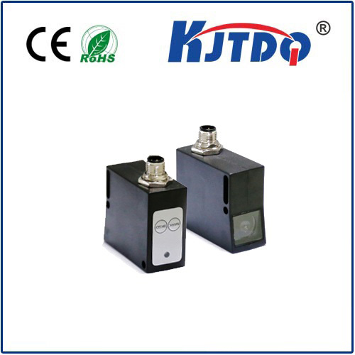
| Inductive |
Eddy currents induced in conductive metal targets |
High-frequency oscillator with a coil; detecting oscillation amplitude/frequency change |
Position sensing in machinery, metal detection, conveyor systems |
| Capacitive |
Changes in capacitance caused by any material object |
High-frequency oscillator with plates; sensitive differential amplifiers |
Level detection (liquids, powders), material presence (glass, wood, plastic) |
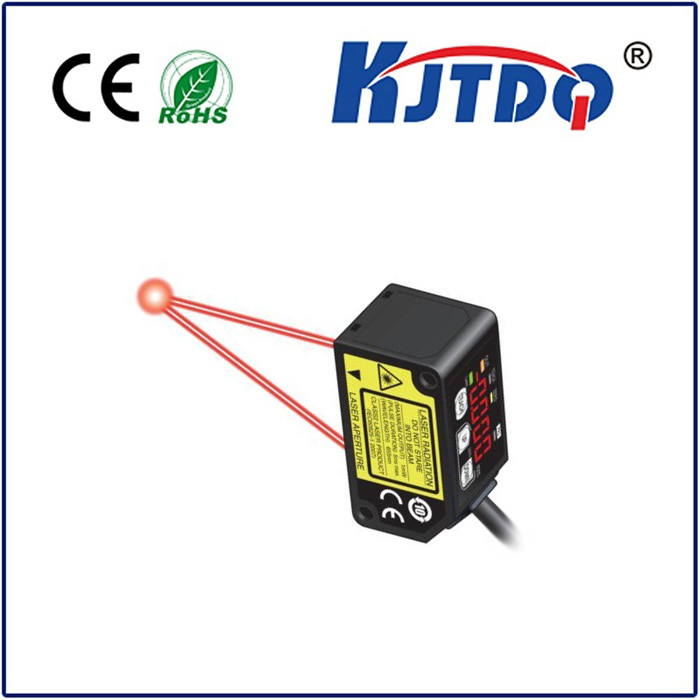
| Infrared (IR) |
Reflection/blocking of modulated infrared light beam |
IR LED drive circuit; sensitive phototransistor amplifier; modulation/demodulation |
Object detection (counters), presence sensing (appliances), touchless interfaces |
| Ultrasonic |
Reflection/echo time of high-frequency sound waves |
Complex transmitter driver for piezoelectric element; sensitive receiver amplifier; time-of-flight measurement |
Distance measurement, object detection over longer ranges, liquid level |
Tailoring the Circuit: Inductive vs. Capacitive vs. Optical
The specific design of the proximity sensor circuit is heavily influenced by the underlying sensing technology:
- Inductive Proximity Sensors: Primarily detect metals. Their circuits are optimized for driving the coil efficiently and detecting minute changes in inductance or energy loss (
Q-factor) with high immunity to non-metallic objects and environmental factors like dust or oil. Coil design and precise oscillator stability are critical. Output transistors are robust to handle industrial switching loads.
- Capacitive Proximity Sensors: Detect nearly any material by sensing changes in dielectric constant. Their circuits require high sensitivity to very small capacitance changes (often femtofarads). They employ sophisticated signal conditioning and shielding techniques to minimize false triggers from environmental factors like humidity. Sensitivity adjustment is often a built-in feature.
- Infrared (IR) Proximity Sensors: Rely on light reflection or interruption. Their circuits must efficiently drive the IR LED (often with pulsed current for lower power consumption and ambient light immunity) and amplify the weak signal from the phototransistor. Sophisticated modulation/demodulation techniques (sending pulses and only “listening” for that specific frequency) are essential to reject ambient visible light. The comparator threshold is crucial for