Проверка
Проверка
Проверка
Проверка
Проверка
Проверка
Building a Laser Transmitter and Receiver System with Arduino: A Step-by-Step Guide Imagine controlling devices, measuring distances, or even creating a secure communication system with just a beam of light. Sounds futuristic? With Arduino, this is not only possible but also surprisingly simple. In this guide, we’ll explore how to build a laser transmitter and receiver system using Arduino, a project that combines creativity, electronics, and coding into one exciting endeavor.
Arduino is a versatile and beginner-friendly microcontroller platform that makes it easy to prototype and implement electronics projects. When paired with a laser diode and a photodiode (or a light sensor), Arduino can process signals and perform tasks like detecting obstacles, measuring distances, or transmitting data. This system is widely used in robotics, security systems, and even DIY communication projects.
Before diving into the project, gather the following components:
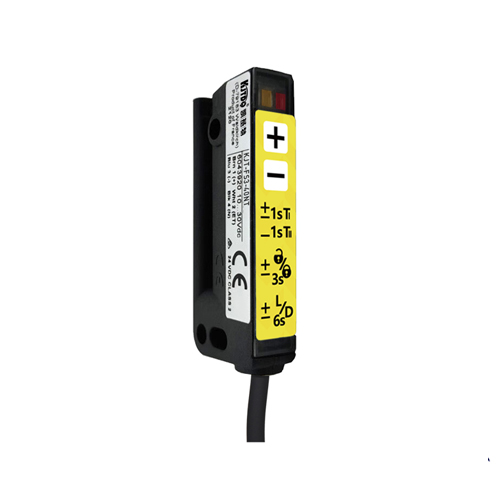
The system operates on a simple principle: the Лазерный передатчик emits a focused beam of light, and the receiver detects it. When the beam is interrupted (e.g., by an object or a person), the receiver sends a signal to the Arduino, which can then trigger an action like turning on an LED or sounding a buzzer. This setup can be expanded for more complex applications, such as data transmission or distance measurement.

The laser transmitter is the simplest part of the system. Most laser diode modules come with built-in resistors, so they can be directly connected to the Arduino. Here’s how to set it up:
The receiver consists of a photodiode or a light sensor module that detects the laser beam. If you’re using a bare photodiode, you’ll need to build a simple circuit with a resistor to convert the light intensity into a voltage signal. However, using a pre-built sensor module simplifies the process. Here’s how to connect a light sensor module:
The Arduino code will read the sensor’s output and determine whether the laser beam is detected. Here’s a basic example:
const int laserPin = 9; // Pin connected to the laser transmitter
const int sensorPin = A0; // Pin connected to the light sensor
void setup() {
pinMode(laserPin, OUTPUT);
digitalWrite(laserPin, HIGH); // Turn on the laser
Serial.begin(9600);
}
void loop() {
int sensorValue = analogRead(sensorPin); // Read the sensor value
Serial.println(sensorValue); // Print the value to the Serial Monitor
if (sensorValue
Explanation: The laser is always on, and the sensor continuously monitors the light intensity. If the beam is interrupted, the sensor value drops below a threshold, triggering an action.
Once everything is connected, upload the code to your Arduino and test the system. Shine the laser beam directly onto the sensor, then interrupt the beam to see if the Arduino detects the change. You may need to adjust the threshold value in the code to account for ambient light.
While the basic setup is great for detecting interruptions, you can expand the project for more advanced applications:
By following this guide, you’ll have a functional laser transmitter and receiver system that can be adapted for various projects. Whether you’re a beginner or an experienced maker, this project offers endless possibilities for creativity and innovation.