laser position sensor arduino

  • time:2025-03-19 01:12:44
  • Нажмите:0

Building a Laser Position Sensor System with Arduino: A Step-by-Step Guide In the world of DIY electronics and robotics, precision measurement tools like laser position sensors have become game-changers. When paired with an Arduino microcontroller, these sensors unlock endless possibilities—from automated alignment systems to interactive art installations. Whether you’re a hobbyist tinkering in your garage or an engineer prototyping industrial solutions, this guide will walk you through how to integrate a laser position sensor with Arduino for accurate, real-time distance and position tracking.

Why Combine Laser Position Sensors with Arduino?

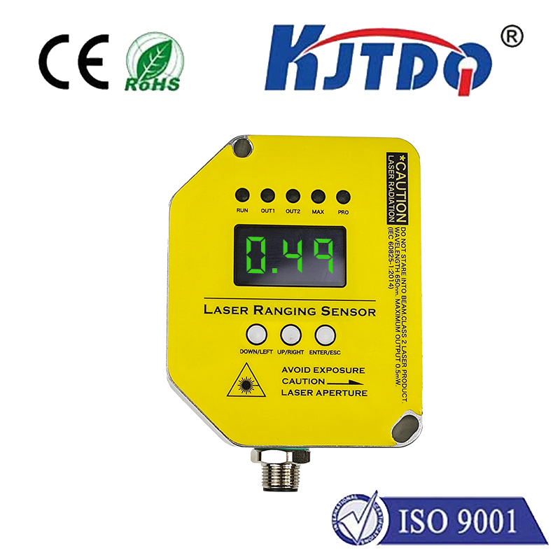
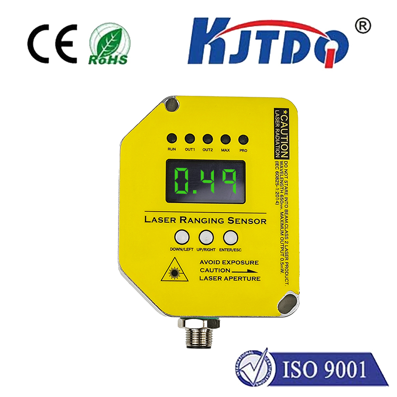
Laser position sensors measure distance or displacement by emitting a focused light beam and analyzing its reflection. Unlike ultrasonic or infrared alternatives, lasers provide sub-millimeter accuracy, making them ideal for applications requiring pinpoint precision. Arduino, with its user-friendly ecosystem and open-source libraries, simplifies the process of interpreting sensor data and triggering responsive actions. This combination is particularly popular in projects like:

  • 3D scanning devices
  • CNC machine calibration
  • Robotic arm positioning
  • Smart security systems

Essential Components for Your Setup

Before diving into the build, gather these components:

  1. Arduino board (Uno or Nano recommended for beginners)
  2. Laser position sensor module (e.g., VL53L0X Time-of-Flight sensor)
  3. Breadboard and jumper wires
  4. Энергоснабжение (5V USB or 9V battery)
  5. Optional: OLED display for real-time feedback

Step 1: Understanding the Sensor’s Working Principle

Most laser position sensors operate on the Time-of-Flight (ToF) principle. The sensor emits a laser pulse and calculates distance by measuring the time it takes for the light to bounce back. For instance, the VL53L0X—a popular Arduino-compatible sensor—can detect objects up to 2 meters away with ±3% accuracy. Pro tip: Avoid using these sensors in direct sunlight or highly reflective environments, as ambient light can interfere with measurements.

Step 2: Wiring the Sensor to Arduino

Connecting a ToF sensor like the VL53L0X to Arduino is straightforward:

  1. VIN5V on Arduino
  2. GNDGND
  3. SDAA4 (Uno) or SDA (Nano)
  4. SCLA5 (Uno) or SCL (Nano) Double-check pin configurations in your sensor’s datasheet. For I²C communication-enabled sensors, ensure you’ve enabled the Wire library in your code.

Step 3: Uploading and Customizing the Code

Install the VL53L0X library via Arduino IDE’s Library Manager. Here’s a basic sketch to get started:

# Включая# Включая
VL53L0X sensor;
void setup() {
Serial.begin(9600);
Wire.begin();
sensor.init();
sensor.setTimeout(500);
}
void loop() {
int distance = sensor.readRangeSingleMillimeters();
Serial.print("Distance: ");
Serial.print(distance);
Serial.println(" mm");
delay(100);
}

This code reads distance data and prints it to the Serial Monitor. For advanced projects, add conditional statements to trigger LEDs, servos, or alarms when thresholds are crossed.

Step 4: Calibration and Testing

Calibration ensures consistent performance:
  1. Place a reference object at a known distance (e.g., 500 mm).
  2. Adjust the sensor’s offset value in code to match the reading.
  3. Test under varying lighting conditions and fine-tune as needed. Did you know? Adding a diffuser to the laser can reduce interference from glossy surfaces.

Creative Project Ideas

  1. Automated Parking Assistant: Mount the sensor on a car model to detect obstacles and alert drivers via buzzers.
  2. Gesture-Controlled Interface: Track hand movements to control RGB lights or music playback.
  3. Precision Farming Robot: Guide a rover to maintain exact spacing between seed-planting holes.

Troubleshooting Common Issues

  • Inconsistent readings: Check for power fluctuations or loose connections.
  • Sensor not detected: Verify I²C addresses using a scanner sketch.
  • Limited range: Ensure the target is within the sensor’s specified operating distance. For deeper customization, explore Arduino forums or GitHub repositories sharing laser triangulation algorithms or multi-sensor fusion techniques.

Optimizing for Performance and Safety

  • Use a heat sink if the laser operates continuously.
  • Pair the sensor with a gyroscope for dynamic orientation tracking.
  • Always follow laser safety guidelines (e.g., Class 1 or 2 lasers for eye-safe projects). By mastering this setup, you’ll join a growing community of makers pushing the boundaries of smart automation and real-time feedback systems. Now, grab your Arduino, fire up that laser, and start measuring your world with unprecedented precision!

Рекомендуемые продукты