laser break beam sensor arduino
- time:2025-03-18 09:38:29
- Нажмите:0
Building a Laser Break Beam Sensor System with Arduino: A Beginner’s Guide
Imagine creating a security alarm that triggers when someone crosses an invisible laser beam or designing a high-speed counter for objects on a conveyor belt—all with components that fit in your pocket. This is the magic of combining a лазерный датчик разрушения луча with an Arduino microcontroller. Whether you’re a hobbyist, educator, or DIY enthusiast, this guide will walk you through the essentials of building and programming a laser beam interruption detection system using affordable, off-the-shelf components.
What Is a Laser Break Beam Sensor?
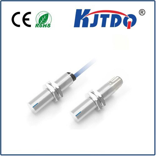
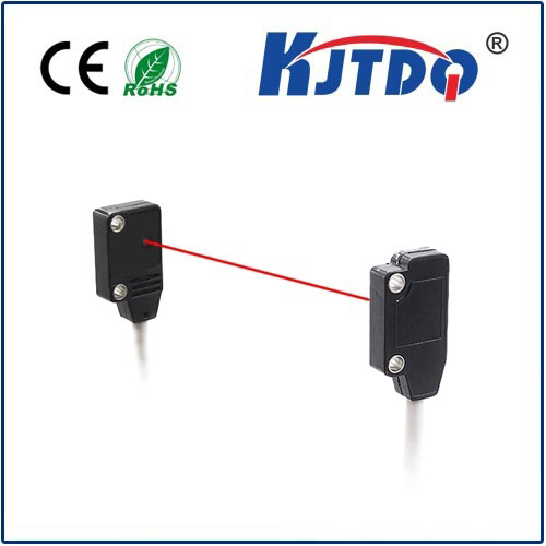
А.лазерный датчик разрушения луча consists of two parts: a laser emitter and a photoresistor (or photodiode) receiver. When the laser beam is uninterrupted, the receiver detects a steady light signal. When an object blocks the beam, the receiver’s output changes, triggering a response. These sensors are widely used in security systems, industrial automation, and even interactive art installations due to their precision and reliability.
Arduino’s versatility makes it ideal for processing signals from such sensors. By pairing the sensor with code, you can create custom logic—like activating an alarm, counting objects, or logging data.

Components You’ll Need
To build this project, gather the following:
- Arduino Uno or Nano (or compatible board)
- Laser diode module (5V)
- Photoresistor or photodiode module
- 10kΩ resistor (for photoresistor voltage divider)
- Breadboard and jumper wires
- Buzzer or LED (for output notification)
Step 1: Circuit Setup
Laser Emitter Connection
Connect the laser module’s VCC and GND pins to Arduino’s 5V and ground. The laser will stay on continuously, creating a visible or infrared beam (depending on the module).
Photoresistor Receiver Setup
- Place the photoresistor in series with a 10kΩ resistor to form a voltage divider.
- Connect one end to Arduino’s 5V, the other to ground, and the middle pin to an analog input (e.g., A0).
- When the laser hits the photoresistor, its resistance drops, increasing the analog read value. Blocking the beam reverses this effect.
Pro Tip: For better accuracy, use a photodiode module with a digital output, which simplifies calibration.
Step 2: Programming the Arduino
Upload this code to detect beam interruptions:
const int sensorPin = A0;
const int buzzerPin = 9;
int baselineValue;
void setup() {
pinMode(buzzerPin, OUTPUT);
Serial.begin(9600);
// Calibrate baseline beam intensity
baselineValue = analogRead(sensorPin);
delay(1000);
}
void loop() {
int currentValue = analogRead(sensorPin);
// Adjust threshold based on ambient light
if (currentValue
Code Explanation
- Calibration: The
baselineValue captures the sensor’s output when the beam is unbroken.
- Threshold Adjustment: The
if statement checks for a significant drop in light intensity (adjust -100 based on testing).
- Экспорт: A buzzer sounds when the beam is blocked, and a message prints to the Serial Monitor.
Key Applications of Laser Break Beam Systems
- Intrusion Detection: Create a perimeter alarm by aligning multiple sensors.
- Количество объектов: Monitor items passing through a production line.
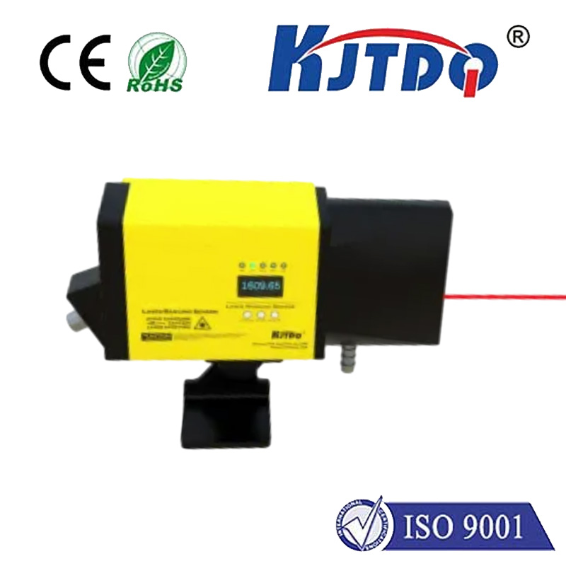
- Speed Measurement: Calculate the velocity of objects by timing beam interruptions.
- Interactive Displays: Trigger lights or sounds when users interact with the beam.
Optimizing Performance
- Ambient Light Interference: Enclose the photoresistor in a tube to block stray light. For outdoor use, opt for infrared laser modules.
- Alignment Tools: Use a laser alignment jig or camera to precisely position the emitter and receiver.
- Power Management: Add a MOSFET to pulse the laser, reducing power consumption and heat.
Troubleshooting Common Issues
- False Triggers: Increase the threshold value or add a delay to ignore brief interruptions.
- Weak Signal: Shorten the distance between the emitter and receiver or use a lens to focus the beam.
- Inconsistent Readings: Ensure stable power supply to the laser and avoid reflective surfaces near the beam path.
Why Choose Arduino for This Project?
Arduino’s analog input pins and real-time processing make it perfect for interpreting sensor data. Its vast library ecosystem allows expansion—for example, adding an LCD display to show interruption counts or connecting to Wi-Fi for remote alerts.
For educators, this project demonstrates core concepts like analog-to-digital conversion, conditional logic, and sensor calibration in a hands-on way.
Taking It Further
Once your basic system works, experiment with:
- Multiple Beams: Create a laser grid for 3D motion tracking.
- Data Logging: Store interruption timestamps on an SD card.
- Wireless Integration: Use Bluetooth or ESP8266 to send alerts to your phone.
By mastering this project, you’ll unlock a world of possibilities in automation and sensing—all powered by a $3 laser and a pocket-sized Arduino board.