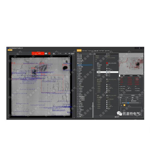
Title: Achieving 0.1mm Precision with Laser Distance Sensors and Arduino: A Step-by-Step Guide Imagine measuring distances with the accuracy of a human hair—0.1 millimeters—using a device you built yourself. For engineers, makers, and robotics enthusiasts, this level of precision opens doors to groundbreaking projects, from automated manufacturing systems to advanced 3D scanning. At the heart of such innovations lies the fusion of laser distance sensors and Arduino microcontrollers, a combination that transforms raw data into actionable insights. In this guide, we’ll explore how to integrate a 0.1mm-resolution laser distance sensor with Arduino, unlocking professional-grade accuracy for DIY applications. Whether you’re designing a CNC machine or a smart measuring tool, this tutorial will equip you with the knowledge to harness laser technology effectively.
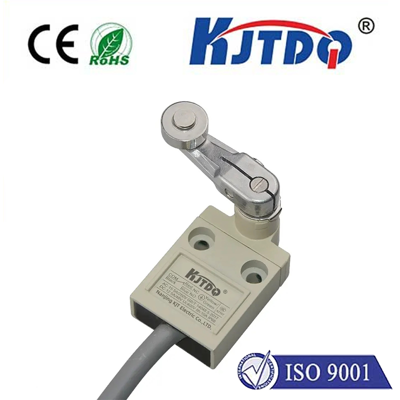
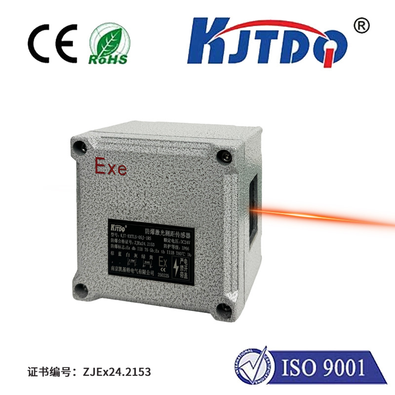
Laser distance sensors use Time-of-Flight (ToF) or triangulation principles to measure distances with exceptional accuracy. Unlike ultrasonic sensors, which struggle with ambient noise, lasers provide reliable results even in challenging environments. The 0.1mm resolution spec means these sensors can detect minute changes, making them ideal for quality control, robotics, and precision alignment tasks. Popular models like the KEYENCE IL-300 or Panasonic HG-C1100 are engineered for industrial use but can be adapted for Arduino projects with minimal effort. Their digital interfaces (I2C, UART) simplify integration, while compact designs ensure versatility in tight spaces.

Not all laser sensors are Arduino-friendly. When selecting a sensor, prioritize:
Let’s assume you’re using a VL53L1X sensor. Here’s how to wire it to an Arduino Uno:
# Включая
VL53L1X sensor;
void setup() {
Serial.begin(115200);
Wire.begin();
sensor.setTimeout(500);
if (!sensor.init()) {
Serial.println("Sensor failed!");
while (1);
}
sensor.startContinuous(50);
}
void loop() {
Serial.print("Distance: ");
Serial.print(sensor.read());
Serial.println(" mm");
delay(100);
}
This code initializes the sensor and prints distance readings every 100ms.
Even high-end sensors require calibration. Follow these steps:
const int numReadings = 10;
int readings[numReadings];
int index = 0;
int getFilteredDistance() {
readings[index] = sensor.read();
index = (index + 1) % numReadings;
long total = 0;
for (int i = 0; i Q: Can I achieve 0.1mm accuracy at long ranges? A: Most budget sensors maintain 0.1mm resolution only up to 1–2 meters. Beyond that, consider industrial-grade models. Q: How does ambient light affect measurements? A: Direct sunlight can interfere. Use sensors with infrared lasers and optical filters. Q: Is Arduino’s 10-bit ADC sufficient? A: For digital sensors, ADC resolution isn’t a concern—they output processed distance values directly. By mastering these techniques, you’ll transform your Arduino into a powerhouse of precision, ready to tackle projects that demand sub-millimeter accuracy.