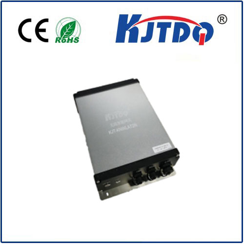

| ON/OFF: | Run button switch | STA: | Running status indicator light |
| PWR: | DC24V Power interface | RS485: | 485 Serial communication port |
| ETH: | Ethernet communication port |
|
|
Device installation
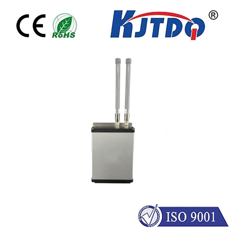
Before powering on, install the antenna first, take out the regulated power supply box and connect it to the PWR, pass the communication network cable through the matching network cable waterproof head and connect it to the ETH, press ON/OFF
Power button, STA flashes quickly and then slowly, indicating normal operation;
The smart gateway and wireless transmitter are paired and installed. The pairing process has been completed by default before leaving the factory. The device ID is affixed to the surface of the product and installed according to the corresponding point table;
The smart gateway is connected to the host computer through a network cable for data transmission, and the transmission protocol is MODBUS TCP.
Pairing point table
| wireless transmitter | Wireless smart gateway | Group No |
| 1 | CH-0, Node: 11 | CH-0, GW: 1 | 1 |
| 2 | CH-1, Node: 12 | CH-1, GW: 2 | 2 |
| 3 | CH-2, Node: 13 | CH-2, GW: 3 | 3
|
