Проверка
Проверка
Проверка
Проверка
Проверка
Проверка
Title: Understanding the Basics of Limit Switch Schematics
In the world of automation and industrial machinery, limit switches are a crucial component for ensuring safe and efficient operation. These devices signal when machinery has reached a certain point in its travel or movement, triggering a response that can range from stopping a motor to sending an alert to an operator. To better understand how these components function within a system, it's essential to grasp the basics of limit switch schematics.
A limit switch schematic is a diagram that illustrates the electrical connection and interaction between the limit switch and the rest of the system it controls. It provides a visual representation of the wiring paths and connections required for proper operation. Understanding this schematic is key for engineers, technicians, and maintenance personnel responsible for designing, installing, and troubleshooting automation systems.

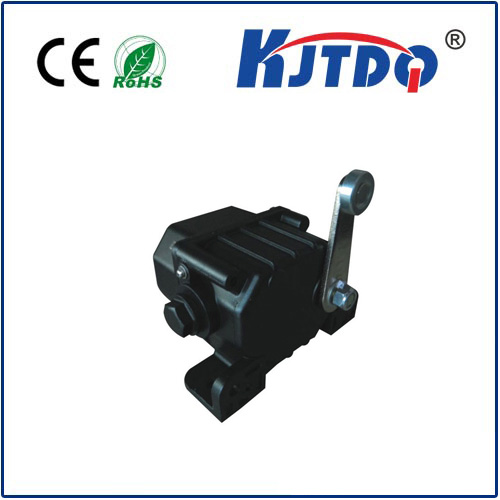
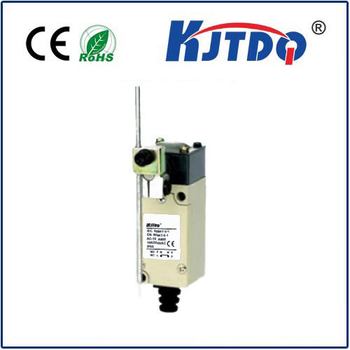
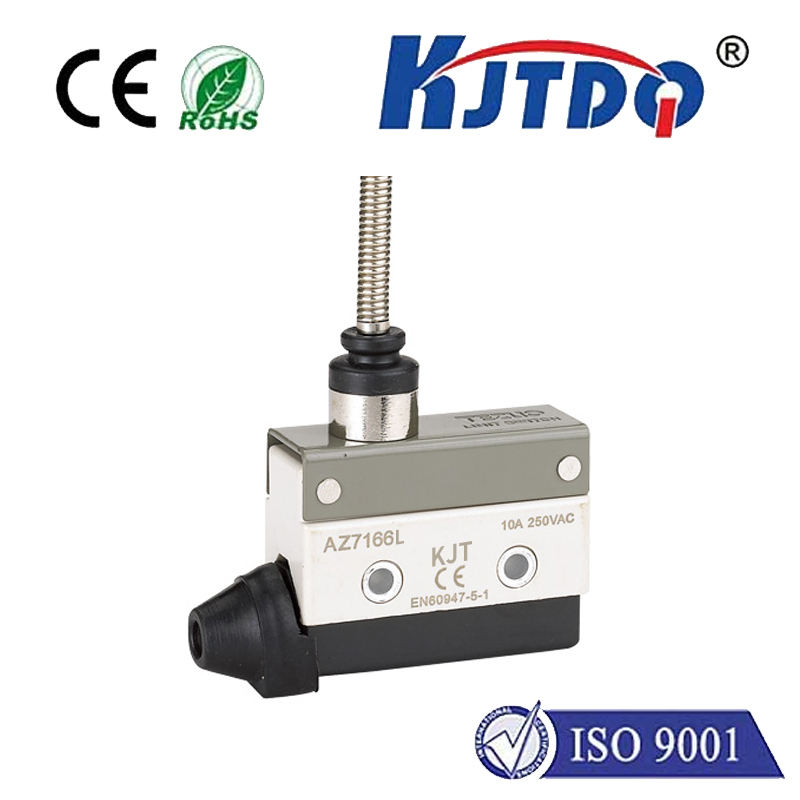
One of the most fundamental elements in a limit switch schematic is the actual limit switch. This component typically includes a lever or roller that activates when it comes into contact with an object, like a machine part or cam. Inside the switch housing, there's usually an electrical mechanism—such as a set of contacts—that closes or opens upon activation, completing or breaking a circuit respectively.
On a schematic, the limit switch will be shown in relation to other components such as motor starters, controllers, and safety interlocks. Wires and cables will be depicted connecting the switch to these elements, with specific symbols indicating the type of wire (such as power, control, or ground) and their purpose within the system.
To further understand limit switch schematics, it’s important to be familiar with common symbols used in electrical drawings. For instance, switches are often represented by rectangles with two or more lines inside indicating their contact arrangement. A circle with a diagonal line represents a normally closed contact, while a circle with a horizontal line inside indicates a normally open contact. Lines entering and exiting these symbols represent the wires connected to the switch.
Another critical aspect of reading limit switch schematics is understanding the control logic. This involves recognizing how the switch affects the flow of electricity and, consequently, the behavior of the machinery. When the limit switch is activated, does it cut power to a motor, or does it send a signal to a programmable logic controller (PLC)? The schematic should clearly show these relationships and interactions.
Safety considerations are also paramount in limit switch schematics. Proper design must ensure that the switch can fail safely—meaning if there's an electrical fault, the switch defaults to a state that prevents harm to equipment or personnel. This may involve additional components such as emergency stop circuitry or redundant switches for critical functions.
Lastly, understanding limit switch schematics means knowing how to interpret the documentation that accompanies them. This includes notes on the specific model and specifications of the limit switch, any special installation requirements, and the intended sequence of operations.
In summary, mastering the language of limit switch schematics equips professionals with the ability to install, maintain, and troubleshoot automation systems effectively. By recognizing the symbols, understanding the control logic, and considering safety measures outlined in these diagrams, one ensures that limit switches perform their role in safeguarding both machinery and human operators alike.