Integrating an Arduino with a limit switch and a stepper motor creates a robust foundation for countless automation and positioning projects. This combination allows for precise control and reliable homing, ensuring your machine operates within safe physical boundaries. Whether you're building a CNC router, a 3D printer, or a custom automated stage, understanding this trio of components is essential.
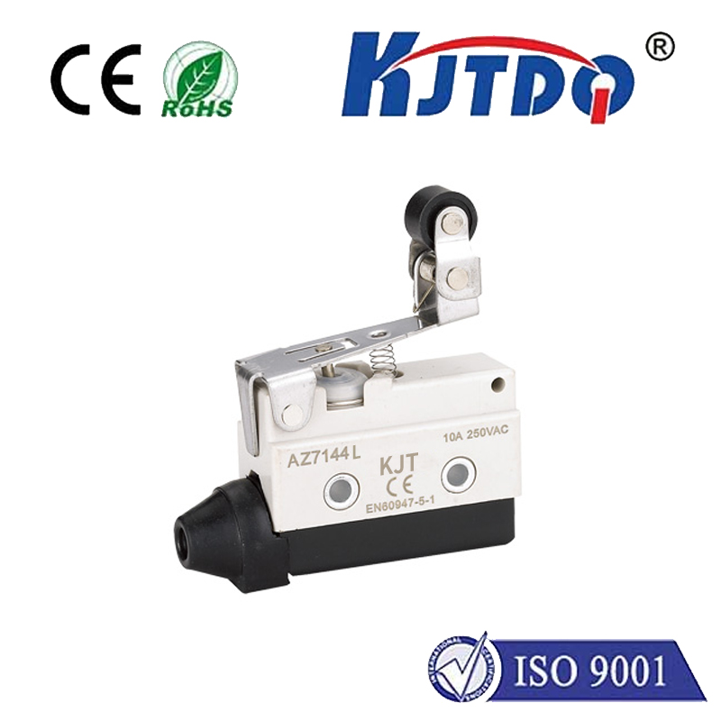
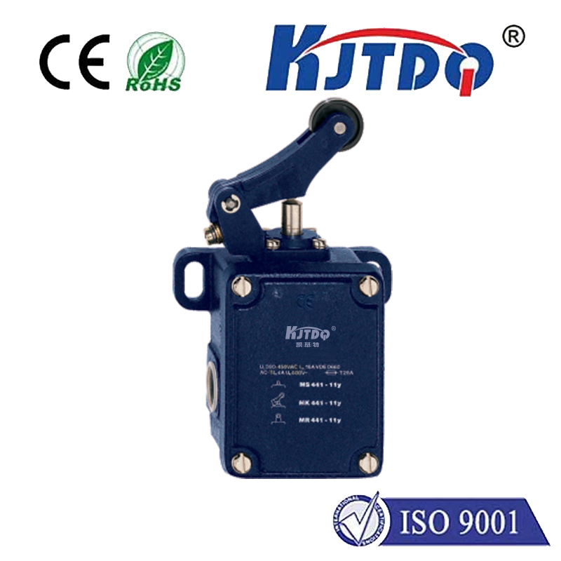
A stepper motor provides accurate motion control by moving in discrete steps. Unlike standard DC motors, you can command a stepper to rotate a specific number of steps, allowing for precise positioning. However, without a reference point, the system doesn't know its absolute position after power-up. This is where the limit switch becomes critical. A limit switch is a simple sensor that acts as a digital button, triggered when a moving part contacts it. It provides a definitive "home" or "limit" signal to the Arduino.
The core function is homing. During a homing sequence, the Arduino instructs the stepper motor to move slowly in one direction until the limit switch is activated. The moment the switch is pressed (changing its state from HIGH to LOW, or vice versa, depending on your wiring), the Arduino immediately stops the motor. This position is now recorded as the known zero point. All subsequent movements can be calculated relative to this home position, eliminating cumulative errors.
To build a basic circuit, you will need an Arduino board (like the Uno), a stepper motor (such as a NEMA 17), a compatible stepper motor driver (like the A4988 or DRV8825), a limit switch (a mechanical micro-switch is common), jumper wires, and an external power supply for the motor. Connect the driver to the Arduino, managing the STEP and DIRECTION pins. Power the driver and motor from the external supply, ensuring the voltage matches your motor's specifications. The limit switch is connected between a digital input pin on the Arduino and ground, typically using a pull-up resistor (either external or the Arduino's internal one enabled in code) so the pin reads HIGH when the switch is open and LOW when closed.
The Arduino code revolves around two main libraries: theStepper library for basic control or, more commonly, theAccelStepper library for advanced features like acceleration and deceleration. The logic is straightforward. In thesetup() function, you initialize the stepper motor and set the limit switch pin as an INPUT_PULLUP. The main loop or a dedicated function contains the homing routine. This routine sets the motor's direction and continuously pulses the motor (usingstepper.runSpeed() or similar) while monitoring the state of the digital pin connected to the switch. Awhile loop often checks for the switch state, exiting only when the switch is triggered. Once triggered, you stop the motor, set the current position to zero (stepper.setCurrentPosition(0)), and potentially move the motor a small distance away from the switch to release it.
Beyond simple homing, limit switches are crucial for safety. You can install two switches: one for the "home" position and another at the far end of travel as a "limit" switch. In your ongoing code, you can constantly check these limit pins during normal operation. If the system ever triggers the far limit, it indicates a potential software error or runaway condition, and the Arduino can execute an emergency stop to prevent damage to the machine or itself. This failsafe mechanism is a hallmark of professional motion control.
Several practical tips ensure success. Always debounce the limit switch signal in software to avoid false triggers from mechanical contact vibration. A simple delay of 10-50 milliseconds after detecting a state change is often sufficient. Position the switch carefully so that the moving part contacts it firmly but does not exert excessive force, which could damage the switch over time. During the homing move, use a slow, consistent speed to ensure reliable and repeatable triggering. For more complex systems with multiple axes, each axis will typically have its own home limit switch.
Troubleshooting common issues involves systematic checks. If the motor doesn't move, verify the driver power and Arduino connections. If the limit switch isn't detected, use the Serial Monitor to print the state of its digital pin and confirm the wiring and pull-up resistor configuration. If the motor doesn't stop precisely at the home position, adjust the homing speed and check for mechanical slop or switch bounce.
Mastering the Arduino, limit switch, and stepper motor integration unlocks advanced project capabilities. It transforms open-loop control into a referenced system, adding layers of repeatability and safety. This fundamental skill is a stepping stone to more complex multi-axis coordinated motion, where precise homing defines the accuracy of the entire system.