Проверка
Проверка
Проверка
Проверка
Проверка
Проверка
Installing limit switches on a Shapeoko CNC router is a crucial upgrade for enhancing safety, precision, and machine longevity. These small but vital components act as sentinels, defining the physical boundaries of the machine's work area. When the router's carriage or spindle touches a switch, it sends an immediate signal to the controller to halt movement, preventing potential crashes into the frame, damaging the workpiece, or harming the stepper motors. For any Shapeoko user, from hobbyists to small workshop professionals, integrating limit switches transforms the machine from a capable tool into a reliable and worry-free workhorse.
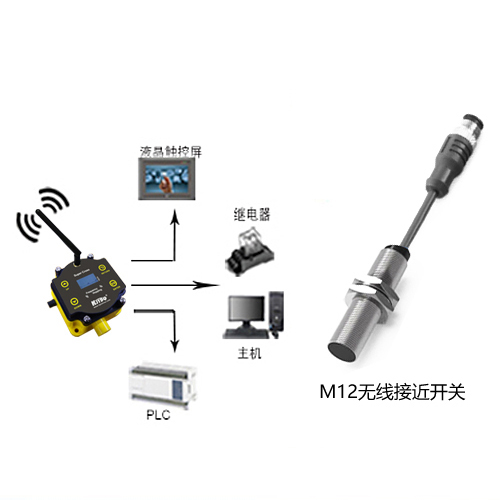
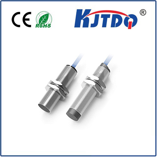
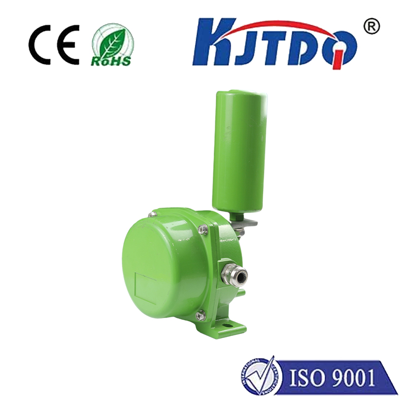
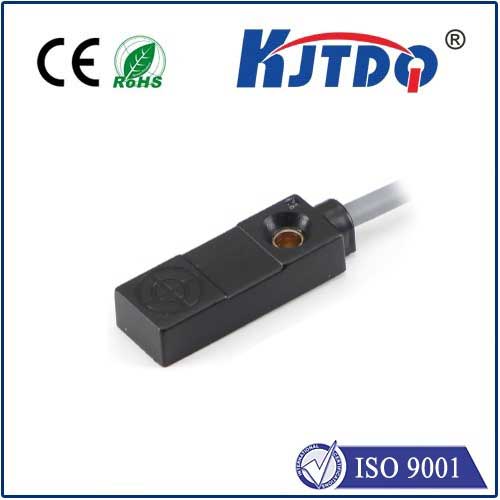
The process begins with understanding the three primary types of limit switches: mechanical, optical, and proximity. Mechanical switches, often the most cost-effective and straightforward for DIY installation, are physically triggered by a moving part. Optical switches use a beam of light and are known for high precision and no physical contact, while proximity switches detect metal without touch. For most Shapeoko models, a set of mechanical end-stop switches offers an excellent balance of reliability and simplicity. The essential tools include the switch kit, wires, a screwdriver, and possibly a soldering iron for secure connections.
Preparation is key. Power down the Shapeoko and disconnect it from the computer. Clear the work area and familiarize yourself with the machine's axis movement—X, Y, and Z. Identify the optimal mounting points. Typically, switches are placed at the negative end (often the rear-left corner) of each axis to define the "home" position. The Shapeoko's T-slot aluminum extrusions provide convenient locations for mounting brackets. Secure the switch brackets firmly using the provided hardware, ensuring they are aligned so that the moving part of the machine will consistently depress the switch's lever.
Wiring requires careful attention. Each switch has two or three terminals. The most common setup involves connecting one wire to the signal terminal and another to the ground, creating a normally open (NO) circuit that closes upon activation. Route the wires neatly along the frame using cable ties, keeping them clear of any moving belts or gears. The wires then connect to the designated limit switch input pins on the Shapeoko's controller board, such as the Carbide Motion board or a GRBL-based controller. Refer to your specific controller's pinout diagram—connecting to the wrong pin is a common error.
After physical installation, software configuration is the next critical step. Within your control software, like Carbide Motion or Universal G-CODE Sender, you must enable the limit switch function in the settings. This often involves adjusting the$H (homing cycle) and$21 (hard limits) parameters in the GRBL configuration. You will need to define the homing direction and the pull-off distance—the small move the machine makes after hitting the switch to release it before establishing the precise home coordinate. Testing is done step-by-step: first, manually trigger each switch with the machine powered and software connected, observing if the movement stops instantly. Then, command a homing cycle to see if the machine correctly moves to each switch and sets its zero position.
Troubleshooting common issues is part of the journey. If a switch is not recognized, double-check the wiring for loose connections or shorts. Verify the software settings and ensure the correct pin is assigned in the firmware. Sometimes, switch bounce—a rapid on-off signal when the lever is pressed—can cause erratic behavior, which may require adding a small capacitor in the circuit or adjusting software debounce settings. Regular maintenance involves occasionally cleaning the switch lever and contact area from dust and debris to ensure reliable triggering.
Ultimately, adding limit switches to your Shapeoko is an investment in seamless operation. It automates the homing process, saving time at the start of every job, and provides an essential layer of protection against costly errors. This upgrade empowers users to push their projects further with confidence, knowing their machine has defined physical limits. The integration of these switches represents a thoughtful step towards mastering CNC workflow, where repeatability and safety become foundational elements of every creation.