In industrial automation and machinery control, precision and reliability are non-negotiable. Among the critical components ensuring seamless operation, the hydraulic limit switch stands out as a robust solution for environments where electrical switches might fail. This device, often overlooked, plays a pivotal role in monitoring and controlling the position of moving parts in heavy-duty applications, from manufacturing presses to construction equipment. Unlike traditional electromechanical limit switches, hydraulic limit switches utilize fluid pressure to actuate, making them inherently resistant to harsh conditions such as dust, moisture, vibrations, and extreme temperatures.
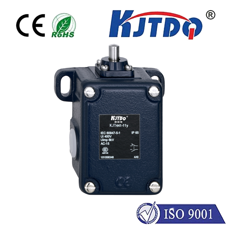
The core mechanism of a hydraulic limit switch involves a simple yet effective design. It typically consists of a piston or diaphragm that moves in response to hydraulic pressure changes. When a machine part reaches a predetermined position, it triggers the piston, which then alters the hydraulic flow or pressure within the system. This change is detected and converted into a control signal, often through an integrated valve or transducer, to stop, start, or adjust machinery operations. This fluid-based actuation eliminates the risk of sparking, a crucial advantage in explosive or flammable environments where electrical components could pose safety hazards.
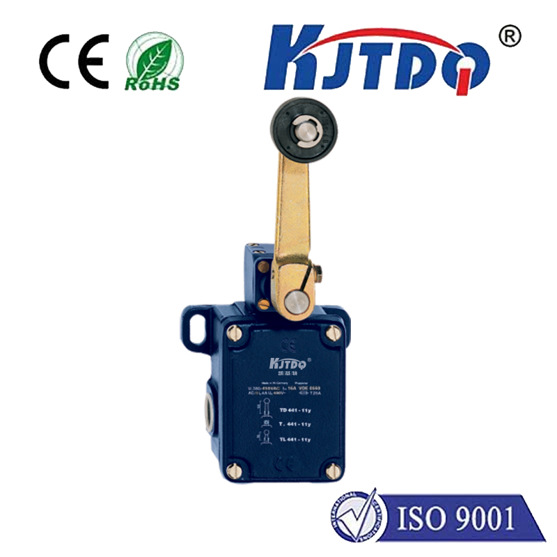
One of the key benefits of hydraulic limit switches is their durability. With fewer moving parts exposed to external elements, they suffer minimal wear and tear, leading to longer service life and reduced maintenance costs. Industries like mining, oil and gas, and marine engineering rely on these switches for their ability to perform consistently under high-pressure scenarios. For instance, in hydraulic presses, they ensure precise stopping points to prevent over-travel and equipment damage, while in agricultural machinery, they help automate processes like lifting and lowering implements with accuracy.
When selecting a hydraulic limit switch, factors such as pressure range, response time, material construction, and compatibility with existing hydraulic systems must be considered. Common materials include stainless steel or brass for corrosion resistance, and seals made from nitrile or Viton to handle various fluid types. Installation is straightforward, often involving direct mounting into hydraulic lines, but proper calibration is essential to avoid false triggers or delayed responses. Regular checks for leaks and pressure drops can further enhance reliability.
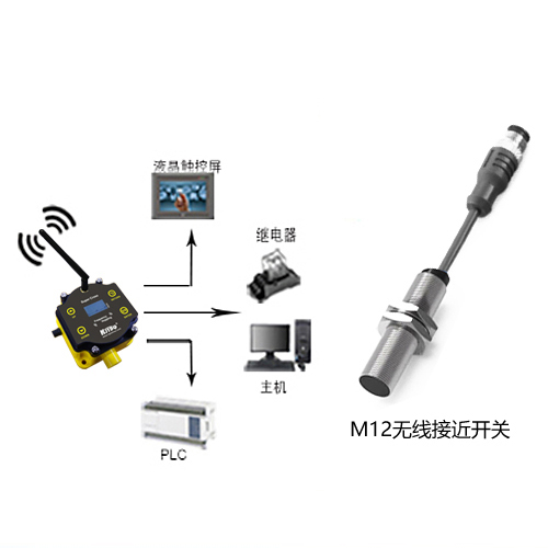
In modern industrial setups, integrating hydraulic limit switches with digital control systems has become increasingly common. By pairing them with sensors and PLCs (Programmable Logic Controllers), operators can achieve real-time monitoring and data logging, enabling predictive maintenance and optimizing workflow efficiency. This synergy between hydraulic robustness and smart technology underscores the evolving role of these switches in Industry 4.0 applications.
Despite their advantages, hydraulic limit switches are not without limitations. They may have slower response times compared to electronic counterparts and require a clean hydraulic fluid supply to prevent clogging. However, for many heavy industries, the trade-off is worthwhile given the enhanced safety and resilience. As automation advances, innovations in hydraulic switch design continue to emerge, focusing on improved sensitivity and eco-friendly fluid options.
Ultimately, the hydraulic limit switch remains a cornerstone in industrial control, offering a dependable alternative where electrical systems fall short. By understanding its operation and applications, engineers and technicians can leverage this tool to boost productivity while ensuring operational safety. Whether in a factory floor or a remote drilling site, its silent, fluid-driven action keeps machinery in check, proving that sometimes, the simplest solutions are the most enduring.