For engineers and maintenance professionals working with industrial machinery, precise control and reliable safety are non-negotiable. The Stromag Limit Switch Series 51 stands as a cornerstone in achieving this, offering robust performance in countless applications. This guide serves as a comprehensive manual for the Series 51, detailing its operation, installation, and maintenance to ensure optimal functionality and longevity.
Understanding the core purpose of the Stromag Series 51 is the first step. This limit switch is an electromechanical device designed to detect the presence or position of a machine part. It acts as a sentinel, sending a critical signal to the control system to either initiate or halt a specific action once a predetermined limit is reached. Common applications include controlling the travel of cranes, positioning gates and doors, and providing end-of-travel safety in conveyor systems. Its durable construction, often featuring a heavy-duty metal housing, makes it suitable for harsh industrial environments where dust, moisture, and mechanical impact are concerns.
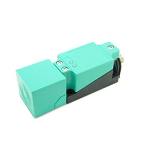
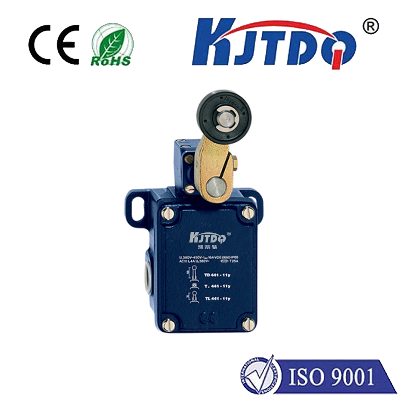
Before proceeding with installation, a thorough inspection of the unit is crucial. Unpack the switch carefully and verify the model number against your order specifications. Check for any visible signs of damage incurred during shipping. Familiarize yourself with the main components: the robust housing, the actuator lever (which comes in various forms like roller lever or fork lever), the terminal block for electrical connections, and the sealing gaskets that ensure ingress protection. The specific actuator type is selected based on the required direction of operation and the physical characteristics of the target machine part.
Installation demands precision and adherence to safety protocols. Always disconnect and lock out all power sources to the machinery before beginning any work. Select a mounting location that is secure, accessible for future maintenance, and where the actuator can engage with the moving target consistently and without binding. The mounting surface must be flat and rigid to prevent vibration-induced misalignment. Use the provided template or drilling holes as specified in the dimensional drawings. Secure the switch using appropriate fasteners, ensuring it is firmly anchored. The next critical phase is adjusting the actuator's operating position. Manually cycle the target machine to its desired limit position. Then, adjust the actuator lever or cam so that the switch triggers reliably at this exact point. Most Series 51 switches allow for fine angular adjustment to achieve this. A common mistake is setting the switch so the actuator is at its extreme position during operation; this can lead to premature wear. Aim for a solid, positive engagement that occurs within the lever's normal range of motion.
Electrical wiring is the next vital step. Refer to the wiring diagram specific to your switch model, which is typically found on the unit's label or in the accompanying documentation. Identify the correct terminals for the power supply, load, and, if applicable, the normally open (NO) and normally closed (NC) contacts. Use copper conductors of the recommended gauge and ensure all connections are tight and secure. Properly route the cable into the conduit entry, using the supplied gland or seal to maintain the switch's IP rating. After wiring is complete and before restoring power, perform a continuity check with a multimeter to verify that the contacts open and close as expected when the actuator is manually operated.
Routine maintenance is key to sustained reliability. Establish a periodic inspection schedule. Visually examine the switch for accumulated dirt, oil, or physical damage. Check the tightness of mounting hardware and electrical terminals, as vibration can loosen them over time. Listen for unusual sounds during operation and observe the actuator's movement for smooth, unrestricted travel. The contacts inside are rated for a certain number of mechanical cycles; keeping a log of operations can help predict end-of-life. For switches in extremely dirty or wet environments, more frequent cleaning of the actuator mechanism may be necessary. Never use high-pressure water or harsh solvents for cleaning, as these can damage seals and internal components.
Troubleshooting often revolves around a few common issues. If the controlled machine fails to stop or start at the limit, first verify the actuator adjustment—it may have shifted or the target may have worn. Next, check the electrical signal at the switch's output with a meter to confirm it is changing state. If the electrical signal is correct, the issue may lie further down in the control circuit. Intermittent operation can point to loose wiring or failing internal contacts. Unresponsive switches often indicate a wiring fault, a blown fuse in the control circuit, or, in rare cases, a mechanical failure inside the switch housing. Always follow a systematic approach: inspect mechanically, then verify electrically.
By following this detailed manual for the Stromag Limit Switch Series 51, you ensure that this critical component performs its duty flawlessly. Correct installation, careful adjustment, and proactive maintenance not only prevent costly machine downtime and enhance safety but also maximize the return on your investment in this industrial workhorse. Its design embodies a commitment to durability, making it a trusted choice for safeguarding machinery and processes across the globe.