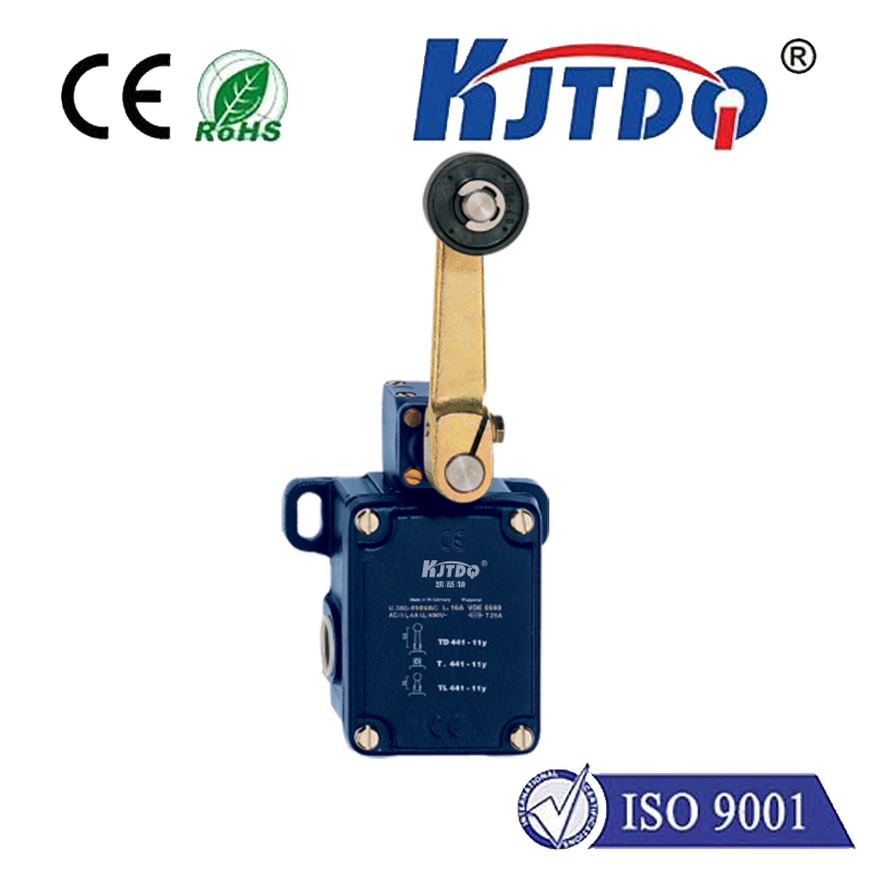
gear cam limit switch
- time:2025-09-14 02:01:46
- Нажмите:0
Gear Cam Limit Switches: Precision Motion Control Essentials
Ever wonder how complex machinery knows exactly when to stop rotating, reverse direction, or trigger an action at a precise point, time after time, often under demanding conditions? That pinpoint accuracy, crucial in automation, manufacturing, and robotics, frequently relies on a specialized and robust component: the Gear Cam Limit Switch. This ingenious device marries mechanical gearing with cam actuation to deliver reliable position sensing and control where standard limit switches might falter.
At its heart, a gear cam limit switch is an electromechanical assembly. Its primary function is to detect the angular position of a rotating shaft and open or close electrical contacts based on pre-set positions. The name reveals its key components:
- Gear: Typically connected directly to the rotating shaft being monitored. This gear meshes with…
- Cam: A specially shaped disc mounted on a secondary shaft driven by the gear. The cam’s profile dictates when the switch will actuate during the rotation.
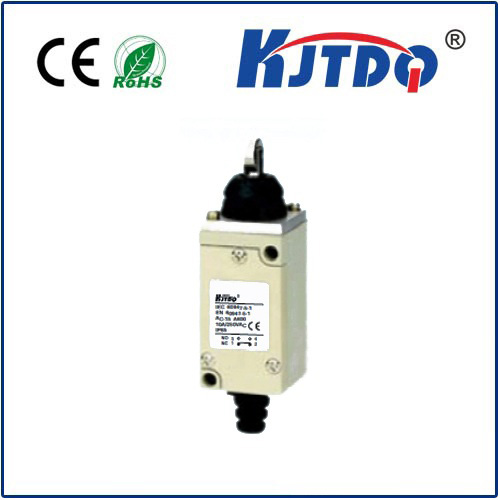
- Limit Switch: The electrical switching element itself, positioned so that a follower or roller rides along the cam’s profile. As the cam rotates, its changing shape physically pushes or releases the switch actuator.
How a Gear Cam Limit Switch Operates: Precision in Motion
The operation is beautifully mechanical yet elegantly effective:

- Input Rotation: The target machine’s shaft rotates.
- Gear Transmission: This rotation drives the input gear of the limit switch assembly.
- Cam Actuation: The input gear turns the cam shaft, rotating the cam profile.
- Follower Interaction: A spring-loaded follower or roller on the switch body faithfully tracks the contour of the rotating cam.
- Electrical Switching: The cam’s shape dictates the follower’s movement. At specific, programmed points in the rotation cycle (determined by high points, lobes, or recesses on the cam), the follower is either pressed inward to actuate the switch contacts or released to allow them to return to their normal state (e.g., normally open closing, or normally closed opening).
- Signal Output: The changing state of the switch contacts generates an electrical signal. This signal is sent to the machine’s control system (like a PLC), indicating that the shaft has reached a critical position. The PLC can then execute commands: stopping a motor, reversing direction, changing speed, starting a process step, or triggering a safety interlock.
Why Choose a Gear Cam Limit Switch? The Distinct Advantages
While simple proximity sensors or basic lever-arm limit switches have their place, gear cam limit switches shine in specific scenarios demanding high precision and ruggedness:
- Exceptional Positional Accuracy: The direct mechanical coupling via gears ensures the signal corresponds exactly to the shaft’s angular position. This accuracy is repeatable and unaffected by factors like vibration or minor alignment shifts that can plague non-contact sensors.
- High Repeatability: Once set, the actuation point is mechanically fixed by the cam profile, providing consistent performance over millions of cycles.
- Robustness & Reliability: Built with durable metal components (gears, cams, hardened switch bodies), these switches excel in harsh industrial environments. They withstand significant shock, vibration, dust, oil, coolant mist, and temperature variations where electronic sensors might fail.
- Multi-Position Control: A single unit, equipped with a multi-lobed cam and potentially multiple switch elements, can provide signals for several different positions within a single rotation (e.g., 0°, 90°, 180°, 270°). This multi-point capability is a key differentiator.
- Independence from Speed: Unlike sensors relying on pulse counting or timing, cam actuation is purely position-based. The switch triggers at the exact spot regardless of whether the shaft is spinning fast or slow.
- Positive Mechanical Actuation: The physical cam pushing the switch provides a definitive, positive action. This avoids potential issues with false triggers from stray magnetic fields or metal chips near inductive sensors.
- Visual Confirmation: Many models offer a clear indication (like a pointer on a dial) showing the current cam position relative to the switch points, aiding setup and troubleshooting.
- High Torque Tolerance: The gear mechanism allows these switches to be used on shafts experiencing significant torque fluctuations without affecting the accuracy of the position signal.
Where Gear Cam Limit Switches Prove Indispensable: Key Applications
Their unique blend of precision, reliability, and ruggedness makes gear cam limit switches vital in numerous demanding applications:
- Промышленная автоматизация: Controlling the start/stop/reversal points of rotating tables, indexers, turntables, and material handling arms. Defining positions for welding robots, assembly stations, and palletizing systems.
- Machine Tools (CNC & Conventional): Indicating spindle orientation for tool changes. Defining rotary table positions for multi-axis machining. Controlling chuck clamping sequences. Signaling the completion of a revolution for threading operations.
- Packaging Machinery: Synchronizing filling, capping, labeling, and sealing stations on rotary platforms. Actuating processes at specific bottle or container positions.
- Перевозка материалов: Controlling the rotation of cranes, hoists, and conveyors. Ensuring bins or ladles are correctly positioned for filling or dumping.
- Printing & Converting: Register control by detecting specific marks or positions on rotating cylinders. Controlling knife cutters or sheeters.
- Process Control: Monitoring and controlling valve positions on motor-operated valves. Defining agitator positions in tanks.
- Robotics: Providing absolute position feedback for rotary joints or end-effector orientation.
Integration and Selection Considerations
Integrating a gear cam limit switch effectively requires careful planning:
- Mounting: Ensure secure, rigid mounting to prevent misalignment or vibration affecting performance. Protection from direct impact or excessive debris may be needed.
- Gear Ratio: The ratio between the driven shaft and the cam shaft determines how many revolutions of the input result in one full revolution of the cam. This sets the resolution for position detection within the machine’s rotation cycle.
- Cam Profile: Select or design a cam profile (e.g., simple lobe, multi-lobe, egg-shaped) that provides the exact actuation points needed for your application. Precision machining of the cam is critical for accuracy.
- Switch Type: Choose switches with the correct electrical rating (voltage, current, AC/DC) and contact configuration (NO, NC, changeover) for the control circuit. Consider environmental sealing (IP ratings).
- Adjustability: Many units offer fine adjustment for setting the exact actuation point relative to the cam position during installation.
In the relentless pursuit of efficiency and precision within automated systems, positively actuated position sensing remains paramount. The gear cam limit switch, with its elegant fusion of gears, a meticulously profiled cam, and a robust switching mechanism, stands as a cornerstone technology. It delivers unparalleled positional accuracy and rock-solid reliability directly from the rotating shaft itself, especially crucial in those demanding environments where less robust solutions cannot endure. When machinery must know its exact rotational position, cycle after cycle, year after year, the mechanical certainty offered by a well-engineered gear cam limit switch is often the optimal choice.


