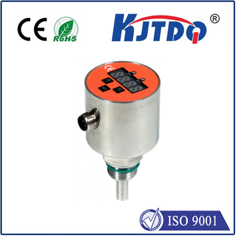
Гидравлический ограничитель
- time:2025-09-12 02:59:57
- Нажмите:0
Hydraulic Limit Switches: Essential Guardians for Precision and Safety
Imagine a massive hydraulic press thundering down, shaping unforgiving steel. What stops it precisely at the critical point, preventing catastrophic damage to itself, the mold, or worse, a worker? Often, the unsung hero is a Гидравлический ограничитель. These robust devices are fundamental components in countless industrial systems, silently ensuring operations run safely and efficiently by monitoring hydraulic cylinder position. Understanding their function and importance is key for anyone involved in fluid power systems and industrial automation.
Unlike their electrical cousins sensing physical contact or proximity, hydraulic limit switches operate based on fluid pressure. They are typically integrated directly into the hydraulic cylinder itself, mounted at specific points along its body or on end caps. Their core function is straightforward yet vital: to detect when a piston within the cylinder reaches a predetermined position during its stroke.
Как работает гидравлический ограничитель?
The principle relies on the interaction between the moving piston and the hydraulic fluid. As the piston travels within the cylinder bore, it displaces fluid. A Гидравлический ограничитель incorporates a small, precisely engineered port or sensing element positioned at the desired trigger point:
- Piston Approach: As the piston moves towards the switch location during extension or retraction, it begins to cover or uncover the switch’s pressure port.
- Pressure Change: This action causes a rapid and detectable change in the fluid pressure within the channel connected to the switch. When the piston seals the port completely, pressure typically spikes; if it uncovers the port, pressure may drop significantly depending on the circuit design.
- Signal Activation: This sudden pressure change mechanically actuates an internal valve or diaphragm within the switch. This mechanical action then triggers an electrical signal – either opening or closing a circuit.
- Control System Response: The electrical signal is sent to the machine’s control system (like a PLC). This signal informs the controller that the cylinder has reached its designated limit position. Consequently, the controller can then command the directional control valve to stop or reverse the cylinder’s motion, initiate the next sequence in a cycle, or trigger a safety interlock.
Why Choose Hydraulic Sensing? Key Advantages

Hydraulic limit switches offer distinct benefits, particularly in harsh environments where electrical sensors might struggle:
- Extreme Environment Resilience: Designed to thrive amidst high pressure, vibrations, temperature extremes (both high and low), contaminants (dust, dirt, moisture), and even potential exposure to hydraulic fluid itself. Their robust housings are often made from hardened steel or other durable materials.
- No Electrical Interference: Being fundamentally mechanical/fluid-based devices for sensing, they are inherently immune to electromagnetic interference (EMI) and electrical noise, which can plague sensitive electronic sensors.
- High Pressure Tolerance: They operate directly within the high-pressure hydraulic lines, eliminating the need for complex sealing arrangements that other position sensing methods might require.
- Simplicity & Reliability: Their mechanism is generally simple, with fewer moving parts prone to failure compared to complex electronic sensors, leading to excellent long-term reliability and lower maintenance needs.
- Cost-Effectiveness: For basic position detection tasks, especially in rugged applications, they often present a more economical solution than sophisticated electronic alternatives.
Where Are They Indispensable?
You’ll find hydraulic limit switches safeguarding operations across a vast array of heavy-duty and mobile equipment:
- Перевозка материалов: Cranes (boom extensions/retractions), forklifts (mast height control), automated guided vehicles (AGVs).
- Construction Equipment: Excavators (boom/arm/bucket positioning), bulldozers (blade height/stroke control), concrete pumpers.
- Agricultural Machinery: Tractors (implement positioning like plows or harvesters), combine harvesters (header height control).
- Forestry Equipment: Harvesters (head positioning), forwarders (crane control).
- Промышленное оборудование: Plastic injection molding machines (clamp position), metal stamping presses (ram position), die-casting machines.
- Mobile Hydraulics: Garbage truck compactors, lift gates, snow plows.
- Marine Applications: Hatch covers, crane operations on vessels.
Key Features to Consider When Selecting
Choosing the right Гидравлический ограничитель is crucial:
- Pressure Rating: Must comfortably exceed the maximum operating pressure of the hydraulic system.
- Port Size & Type: Needs to match the fitting specifications of the cylinder or manifold it will be installed into (e.g., NPT, SAE, BSPP, BSPT, metric).
- Electrical Specifications: Voltage, current rating, and electrical connection type (e.g., spade terminals, DIN connector, flying leads) must align with the control system requirements. Common outputs are simple SPST (Single Pole, Single Throw) or SPDT (Single Pole, Double Throw) switches.
- Adjustability: Some switches offer adjustable set points, allowing fine-tuning of the trigger position after installation, which can be invaluable during setup and maintenance.
- Housing Material & Protection: Must withstand the environmental conditions (corrosion resistance, impact resistance). Look for ratings like IP (Ingress Protection) for dust/water resistance.
- Temperature Range: Ensure the switch’s operating temperature range covers the application’s extremes.
Installation and Maintenance Best Practices
Proper installation is paramount for reliable operation:
- Ensure the mounting location on the cylinder provides accurate detection of the piston position without interference.
- Tighten connections meticulously to standard torque specifications to prevent leaks and potential blow-out under high pressure. Use appropriate thread sealants where required (avoiding tape on certain sealing surfaces).
- Route electrical wiring securely away from heat sources, sharp edges, and moving parts, using conduit or protective sleeving as needed.
Техническое обслуживание is generally minimal due to their robustness, but periodic checks are wise:
- Inspect for hydraulic leaks around the switch body or fittings during routine system checks.
- Verify the integrity of electrical connections for corrosion or looseness.
- Functionally test the switch operation during machine preventative maintenance cycles to ensure it reliably triggers at the correct position.
In the demanding world of hydraulics, hydraulic limit switches remain a cornerstone technology for position feedback and safety interlocks. Their unique ability to operate reliably under punishing conditions, immune to electrical noise, makes them the go-to choice for countless critical applications. While more advanced sensing technologies exist, the simplicity, ruggedness, and cost-effectiveness of the hydraulic limit switch ensure its continued vital role as a guardian of industrial precision and safety.