iso 13849 sensor photoelectric
- time:2025-09-12 01:56:27
- Нажмите:0
Unlocking Safety Compliance: Photoelectric Sensors and ISO 13849
Every machine carries inherent risk. In the high-stakes world of industrial automation, where human operators interact with powerful equipment daily, mitigating these risks isn’t just ethical—it’s a legal and economic imperative. Accidents cause human suffering, costly downtime, and reputational damage. Photoelectric safety sensors stand as critical guardians at the perimeter of danger zones, but their effectiveness hinges on integration within a rigorously designed safety system. That’s where ISO 13849 enters the picture. This globally recognized standard provides the blueprint for designing and validating safety-related parts of control systems (SRP/CS), ensuring machinery achieves the necessary Performance Level (PL) to protect personnel. Understanding how photoelectric safety sensors align with ISO 13849 is paramount for engineers and safety professionals tasked with creating genuinely safe working environments.
Deciphering ISO 13849: The Safety Blueprint
ISO 13849-1, specifically, deals with the principles for designing and integrating safety-related control systems. Its core objective is to ensure these systems reliably perform their safety function when required. The standard achieves this through several key concepts:
- Determining the Required Performance Level (PLr): This is the starting point. Based on a risk assessment (often guided by standards like ISO 12100), engineers identify the necessary level of risk reduction the safety function must provide. PLr ranges from PLa (lowest risk reduction) to PLe (highest risk reduction). Factors considered include severity of potential injury, frequency of exposure to the hazard, and possibility of avoiding the hazard.
- Achieving the PL via Design: Once PLr is known, ISO 13849 specifies how to design the safety-related control channel (including sensors, logic, and actuators) to meet or exceed that level. This involves selecting components and architectures that provide sufficient:
- Diagnostic Coverage (DC): Measures how effectively the system can detect internal faults. Higher PLs demand higher DC.
- Mean Time To Dangerous Failure (MTTFd): A probabilistic measure of the safety-related parts’ reliability concerning dangerous failures.
- Structure (Category): Defines the architectural principles to achieve fault tolerance. Categories (Cat.) range from B (basic safety principles) to 4 (highest fault tolerance, typically requiring redundant channels with monitoring). Higher PLs require higher Categories and correspondingly robust designs.
- Validation: After design, the system must be validated to prove it meets the calculated PL.
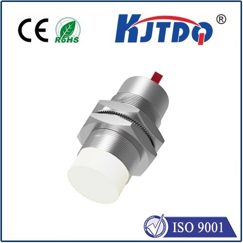
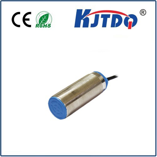
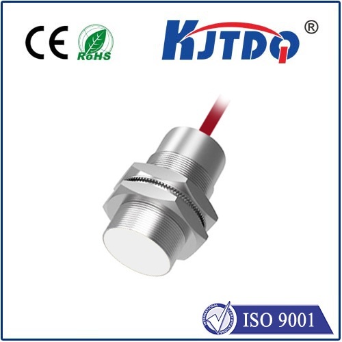
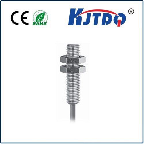
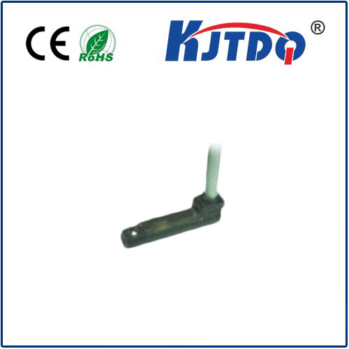
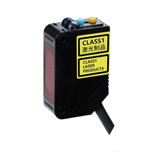
Photoelectric Safety Sensors: Guardians at the Gate

Photoelectric safety sensors are non-contact devices used to detect the presence or absence of personnel or objects within hazardous areas. They create an invisible light beam or field. Breaking this beam, or detecting presence within a defined zone, triggers the safety function – typically initiating a machine stop (Safe Torque Off - STO or similar) via the safety controller.
Common types include:
- Safety Light Curtains (SLCs): Arrays of synchronized light beams creating a detection screen. Used for point-of-operation guarding (e.g., robotic cells, presses).
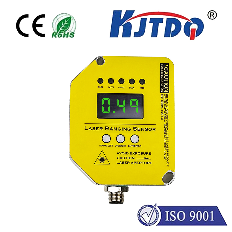
- Safety Laser Scanners: Create two-dimensional protection fields (warning and stopping zones) around mobile robots or large machinery.
- Safety Light Barriers: Single or dual-beam devices for perimeter guarding or access point monitoring.
Why ISO 13849 is Crucial for Photoelectric Safety Systems
Simply installing a photoelectric sensor does not guarantee safety. ISO 13849 provides the framework to systematically ensure the entire safety function, from detection to reaction, is reliable enough for its intended risk reduction level (PLr). Here’s why the standard matters for these sensors:
- Defining Sensor Requirements: The required PLr directly dictates the necessary performance characteristics of the photoelectric sensor itself.
- Sensors intended for high PLr (e.g., PLe) must be designed to higher Categories (typically Cat. 3 or 4). This involves internal redundancy, self-monitoring circuits for faults like LED failure or dirty optics, and high MTTFd values. A basic sensor lacking diagnostics might only suffice for lower PLr/Cat.
- Integrating into the System PL: The sensor is just one component (subsystem) in the SRP/CS chain. ISO 13849 mandates calculating the overall PL for the safety function by considering the PL of each subsystem (sensor, logic, actuator) and their combination. The sensor’s specified PL (achieved through its design and validated by the manufacturer) is a critical input to this calculation. A sensor rated for only PLc cannot be used to achieve an overall system PLr of PLe.
- Ensuring Compatibility: Output types (OSSDs - Output Signal Switching Devices) and interfacing requirements must be compatible with downstream safety controllers, adhering to the architectural principles (Category) needed for the PLr. Signals need appropriate processing and monitoring within the logic solver.
- Addressing Common Cause Failures (CCF): ISO 13849 requires analysis to prevent a single fault from incapacitating multiple safety channels. This impacts sensor selection and installation (e.g., physical separation of redundant beams in a light curtain).
- Validation Basis: The standard provides the quantitative and qualitative methods needed to validate that the combined system, including the photoelectric sensor, achieves the required PL. Manufacturers provide crucial data (MTTFd, DC, B10d values for mechanical components, Category, PL) in their documentation to support this calculation.
Key Compliance Considerations When Selecting Sensors
- Manufacturer’s Declaration: Always look for the sensor’s certified Performance Level (PL) and Category. Reputable manufacturers provide detailed certificates and documentation explicitly stating these parameters based on ISO 13849 validation. Never assume performance.
- Diagnostic Coverage (DC): High DC is essential for high PLr. Sensors for Cat. 3⁄4 architectures must have sophisticated self-monitoring (e.g., monitoring light intensity, receiver function, internal circuitry).
- MTTFd Values: Check the Mean Time To Dangerous Failure figures provided for the sensor’s critical components. Higher values contribute to achieving higher PLs. Refer to manufacturer data.
- Output Configuration: Ensure the sensor’s safety outputs (OSSDs) meet the needs of the chosen Category (e.g., two independent cross-monitored OSSDs for Cat. 4) and are compatible with the safety controller’s inputs.
- Setup and Muting Functions: If using muting (temporarily disabling the safety field for material passage) or blanking (ignoring specific beams within a curtain), these functions must themselves be designed and validated according to ISO 13849. Auxiliary safety devices like mute sensors are part of the SRP/CS. Incorrectly implemented muting is a major safety risk.
- Environmental Suitability: Consider factors like ambient light immunity, resistance to shock/vibration, temperature range, and ingress protection (IP rating) to ensure reliable operation and maintain the designed MTTFd.
Implementing for Success: Beyond Component Selection
Selecting an ISO 138498-compliant photoelectric sensor is vital, but it’s only part of the solution. Successful implementation requires:
- Accurate Risk Assessment: Establishing the correct PLr upfront.
- System-Wide Design: