photoelectric sensor circuit
- time:2025-09-12 01:19:23
- Нажмите:0
Photoelectric Sensor Circuits: How They Work & Real-World Applications
Imagine machines that can “see” objects without physical contact, detecting presence, position, colour, or even cleanliness. This isn’t science fiction; it’s the everyday reality powered by photoelectric sensor circuits. These ingenious electronic systems form the backbone of countless automated processes, from manufacturing assembly lines to your office printer and supermarket checkout. At their core, they leverage the fundamental interaction between light and matter, translating photons into actionable electrical signals. Understanding how these photoelectric sensor circuits function unlocks the door to appreciating their pervasive role in modern technology.
The Core Principle: Light Becomes Signal
The magic starts with the photoelectric effect. Simply put, when light particles (photons) possessing sufficient energy strike certain materials (like semiconductors in photodiodes or phototransistors), they can dislodge electrons, generating an electrical current or changing the material’s resistance. A photoelectric sensor circuit harnesses this principle. It consists, fundamentally, of two key parts integrated within an electronic circuit:
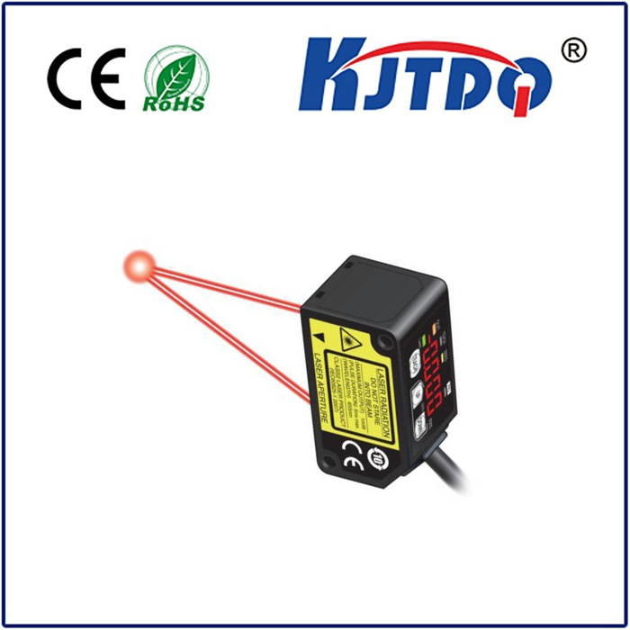
- The Emitter (Light Source): Typically, this is an infrared emitter (like an IR LED) due to its efficiency, long life, and invisibility to the human eye. However, visible red LEDs, laser diodes, or even specialized white light sources are used depending on the application. This component generates the modulated light beam directed towards the target area.
- The Receiver (Light Detector): This is the component sensitive to the emitted light. Common detectors include phototransistors, photodiodes, or sometimes photodarlingtons for higher sensitivity. Their electrical properties (current, resistance, voltage) change significantly when illuminated by the specific wavelength of light from the emitter.
The Circuitry: Bridging Detection and Action

The elegance of the photoelectric sensor circuit lies in how it processes the receiver’s response. The circuit isn’t just the components; it’s the carefully designed electronics that interpret the light signal and produce a usable output. Key circuit blocks include:
- Emitter Driver: Controls the infrared emitter or other light source, often pulsing it at a high frequency. This modulation helps the sensor ignore constant ambient light sources (like sunlight or room lights), significantly improving reliability and reducing false triggers.
- Receiver Amplifier: The signal generated by the phototransistor or photodiode is usually very small. An amplifier stage boosts this signal to a level usable by the logic circuits. Sophisticated circuits incorporate automatic gain control (AGC) to handle varying signal strengths.
- Comparator/Demodulator: This critical stage determines if the received light signal meets the threshold to be considered “present.” For modulated light, the circuit demodulates the signal, essentially checking if it matches the emitter’s pulse pattern. A comparator compares the amplified signal against a set reference voltage. Output switching occurs when the signal crosses this threshold (e.g., beam blocked or reflected beam received).
- Output Stage: Translates the detection decision into a practical form. Common outputs include:
- Digital Output (NPN/PNP Transistor): Provides a simple ON/OFF signal compatible with PLCs (Programmable Logic Controllers) or microcontrollers. This is the most common object detection signal.
- Analog Output: Provides a varying voltage or current proportional to the received light intensity, used for tasks like distance measurement (using triangulation) or opacity detection.
- Relay Output: Used for switching higher-power loads directly.
The Three Main Flavors: Choosing the Right Detection
Photoelectric sensors achieve detection in three primary ways, each suited to different scenarios and implemented with specific circuit nuances:
- Through-Beam (Opposed Mode): The emitter and receiver are housed in separate units facing each other directly. Detection occurs when an object physically interrupts the light beam between them. This offers the longest sensing range and highest reliability, ideal for large objects or demanding environments. The photoelectric sensor circuit on the receiver side reacts to the absence of the expected light signal.
- Retroreflective: Both emitter and receiver are housed in a single unit. A specialized reflector (corner-cube or tape) bounces the emitted light beam directly back to the receiver. Detection occurs when an object breaks the beam path to the reflector. The circuit detects the loss of the strong reflected signal. This offers a good sensing range and simpler installation than through-beam, requiring wiring only on one side. Polarizing filters are often used to distinguish the reflector’s signal from shiny objects.
- Diffuse (Proximity Mode): Both emitter and receiver are in a single unit. The sensor detects light reflected diffusely off the target object itself. No separate reflector is needed. Detection range is typically shortest and heavily dependent on the object’s colour, size, and surface texture (light objects reflect better). The photoelectric sensor circuit must be highly sensitive to detect the relatively weak scattered light signal returning to the receiver. Background suppression variants use triangulation principles to only detect objects within a specific distance band.
Where the Circuit Shines: Ubiquitous Applications
The robustness, versatility, and non-contact nature of photoelectric sensor circuits make them indispensable across industries:
- Промышленная автоматизация: Fundamental for object detection on conveyor lines (counting, jam detection, positioning), bottle/can presence in filling machines, robotic part positioning, machining tool control, end-of-travel limits, and palletizing/depalletizing.
- Packaging & Material Handling: Detecting labels, checking fill levels (transparent containers), verifying case sealing, counting items, and triggering diverters or gates. Photoelectric circuit reliability ensures smooth logistics.
- Security Systems: Used in beam-break systems for perimeter protection, door/gate monitoring, and light curtain safety barriers preventing access to hazardous machinery.
- Consumer Electronics & Appliances: Paper detection in printers/copiers, disc tray positioning, level sensing in vending machines, and door closure detection in microwaves or refrigerators often rely on compact, cost-effective photoelectric circuits.
- Building Automation: Controlling automatic doors, counting people, smoke detection (in some types), and light dimming based on occupancy.
- Transportation: Vehicle detection at toll booths, train car counting, and triggering wash systems.
Design Considerations: Ensuring Reliability
Implementing a successful photoelectric sensor circuit involves more than just the schematic. Environmental factors significantly impact performance:
- Ambient Light: Modulated light sources and optical filters are crucial to combat interference from sunlight or artificial lighting. Signal processing within the circuit filters out non-matching frequencies.
- Target Characteristics: The object’s colour, reflectivity, size, and surface finish dictate the optimal sensor type (diffuse, retro) and required sensitivity settings. Dark, matte objects absorb more light, making detection harder for diffuse sensors.
- Operating Environment: Exposure to dust, dirt, fog, steam, or chemicals necessitates choosing sensors with appropriate ingress protection (IP) ratings. Optics can become dirty, requiring maintenance or specific lens designs. Temperature extremes affect component performance.
- Electrical Noise: Factories are electrically noisy. Shielding cables, using differential signaling where possible, and robust circuit grounding are essential to prevent false triggering.
- Mounting & Alignment: Especially critical for through-beam and retroreflective sensors, precise alignment ensures the beam hits the receiver or reflector correctly. Vibration resistance is often necessary.
From the invisible pulse of an **inf