proximity sensor datasheet
- time:2025-09-07 05:28:46
- Нажмите:0
Proximity Sensor Datasheet: Your Essential Guide to Selection & Integration
Imagine having a powerful tool but no instruction manual. That’s often the predicament engineers face when integrating components without thoroughly consulting their datasheets. For proximity sensors, the unsung heroes enabling touchless detection in countless applications from smartphones to factory automation, the datasheet isn’t just a reference – it’s the critical blueprint for successful implementation. Ignoring its details can lead to costly errors, system failures, and frustrating debugging sessions. This guide demystifies the proximity sensor datasheet, empowering you to unlock its vital information and make informed design choices.
Why the Proximity Sensor Datasheet is Non-Negotiable
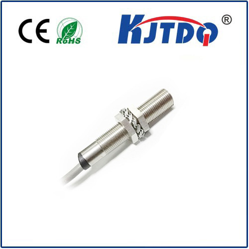
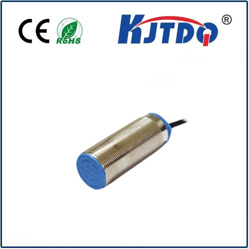
Proximity sensors are diverse. They come in various technologies – inductive, capacitive, photoelectric, ultrasonic – each with distinct operating principles and performance characteristics. The datasheet is the authoritative source that translates abstract sensor capabilities into concrete, measurable parameters relevant to your specific application. It provides the hard data needed to answer fundamental questions: Will it detect my target material at the required distance? Can it withstand the environmental conditions? How will it interface with my control system? Relying solely on generic descriptions or vendor summaries risks mismatches that derail projects.

Decoding Key Specs: Beyond the Basics
While electrical ratings (supply voltage, current consumption) are always crucial, proximity sensors demand deeper scrutiny of specific parameters:
- Sensing Distance/Operating Distance: Often called Sn. This is arguably the most sought-after figure. Crucially, datasheets specify this under standardized conditions (usually a defined target material, size, and environmental setup). Never assume this is an absolute maximum under all circumstances! Understand the test conditions (e.g., “Fe 1mm x 1mm square”). For non-ferrous capacitive sensors, the dielectric constant of the target significantly impacts results.
- Assured Operating Distance (Sa): This is the guaranteed range within which detection will occur reliably, considering manufacturing tolerances and specified environmental factors like temperature. Sa is typically 70-90% of Sn. Designing to Sn risks intermittent failures; design using Sa for robustness.
- Hysteresis (H): The difference between the switch-on point (as the target approaches) and the switch-off point (as the target moves away). Specified as a percentage of Sn or in millimeters. Adequate hysteresis prevents chattering (rapid on/off switching) when the target lingers near the detection threshold.
- Response Time: How quickly the sensor reacts to a target appearing or disappearing. Critical for high-speed applications (e.g., counting objects on a fast conveyor). Note if rise time (target approaching) and fall time (target departing) differ.
- Output Configuration & Type:
- NPN vs. PNP: Defines the transistor switching logic. Mismatching this with your PLC or controller input is a common integration error. The datasheet diagram is your friend here.
- NO (Normally Open) vs. NC (Normally Closed): Describes the output state when Нет! target is present.
- Analog Output: If applicable, note the range (e.g., 0-10V, 4-20mA) and linearity/sensitivity relative to distance.
- Switching Frequency: The maximum number of on/off cycles per second the sensor can reliably handle. Vital for high-speed detection tasks.
- Environmental Ratings:
- IP Rating (Ingress Protection): Essential! Determines resistance to dust and moisture (e.g., IP67 for dust-tight and temporary immersion). Match this rigorously to your operating environment.
- Temperature Range: Specifies storage, operating ambient, and reflow soldering (if applicable) limits. Ensure suitability for your application’s thermal conditions. Consider derating sensing distance at temperature extremes.
- Material & Target Dependencies: Especially critical for inductive and capacitive sensors:
- Inductive: Primarily detect ferrous metals (steel, iron). Detection distance reduces significantly for non-ferrous metals (aluminum, brass, copper) – datasheets often provide a correction factor. Target size also matters.
- Capacitive: Detect a wide range of materials (liquids, plastics, wood, metals) but performance varies dramatically with the target’s dielectric constant. Datasheets usually specify Sn for a standard material (like metal). Understand adjustments needed for your target.
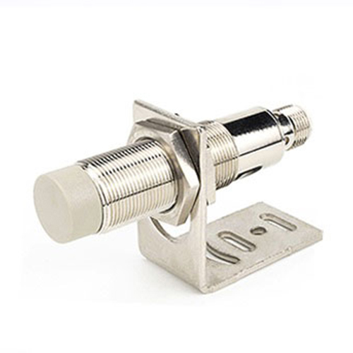
- Mounting Information: Includes flush-mounting (shielded) vs. non-flush mounting (unshielded) characteristics, which directly impact sensing distance and interference susceptibility. Dimensions, tolerances, and recommended clearances to metal are also detailed.
Interpreting Graphs & Curves: The Nuanced Picture
Beyond tables, datasheets often contain insightful graphs:
- Sensing Distance vs. Supply Voltage: Shows how Sn might fluctuate with voltage variations. Ensures performance across your expected supply range.
- Sensing Distance vs. Ambient Temperature: Illustrates the дрейф температуры – how Sn changes as temperature deviates from 25°C. Critical for precision applications or harsh environments.
- Response Time vs. Temperature: How quickly the sensor reacts under varying thermal conditions.
- Hysteresis Diagram: Visualizes the switch-on and switch-off points relative to target distance.
Practical Application: Putting the Datasheet to Work
- Define Your Requirements: Before opening a datasheet, clearly outline your application needs: target material/size, required detection range, environmental conditions (temp, moisture, chemicals), electrical interface needs (voltage, output type), physical constraints.
- Compare Technologies: Narrow down your search based on your target (inductive for metal, capacitive for non-metals/liquids, photoelectric for presence/absence, ultrasonic for distance). Datasheets are invaluable for this initial filtering.
- Scrutinize Key Parameters: Match your requirements directly to the specs: Is Sa sufficient? Does the IP rating meet the environment? Does the output type (NPN/PNP, NO/NC) integrate with your controller? Is the response time fast enough?
- Consider Environmental Effects: Adjust your required sensing distance based on temperature drift data and potential target material correction factors.
- Plan Mounting: Refer to dimensional drawings and mounting notes to ensure proper installation clearances and performance (flush vs. non-flush).
- Interface Correctly: Double-check electrical connections using the wiring diagrams. Verify load compatibility (max current).
- Account for Tolerances: Build your mechanical design using Sa (not Sn), and consider component tolerance stack-ups. Leave a margin for reliability.
Investing Time Saves Headaches
Mastering the proximity sensor datasheet is an investment that pays substantial dividends. It prevents costly selection errors, reduces integration time, minimizes field failures, and ensures optimal performance. View it not as a hurdle, but as your indispensable partner in harnessing proximity sensing technology effectively. The next time you select a sensor, make the datasheet your first and most thoroughly consulted resource – it holds the precise details that transform a generic component into the perfect solution for your unique application. Remember, in the world of sensing, precision starts with understanding the specifications.