proximity sensor cable
- time:2025-09-06 05:58:09
- Нажмите:0
Proximity Sensor Cable: The Silent Partner Ensuring Reliable Detection
Think about the last time an elevator door magically slid open without you touching it, or your car warned you about an unseen obstacle while parking. Behind these seemingly simple interactions lies a sophisticated network of sensors, and crucially, the proximity sensor cable that brings their vital signals to life. Often overlooked, this unassuming component is the indispensable lifeline, ensuring the accurate and uninterrupted flow of detection data that powers modern automation, safety systems, and countless smart devices.
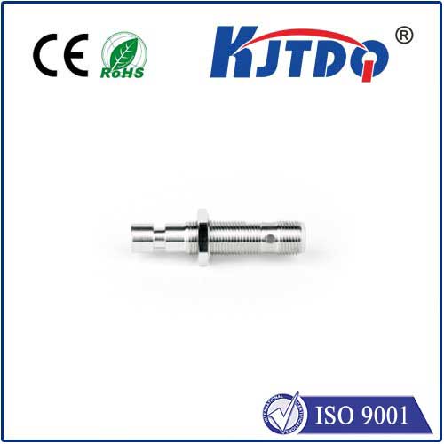
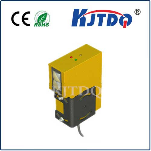
Proximity sensors themselves are marvels of engineering, detecting the presence or absence of objects without physical contact – using magnetic fields, capacitance changes, or light. But without a reliable connection back to the control system (PLC, microcontroller, etc.), their capability is nullified. This is where the specialized proximity sensor cable steps in. It’s far more than just wires; it’s a precision-engineered conduit designed to handle the specific requirements of sensor signals in demanding environments.

Why Standard Cables Fall Short
Using generic wiring for proximity sensors is a recipe for unreliability and signal degradation. Proximity sensors typically output low-voltage, low-current signals that are highly susceptible to:
- Electromagnetic Interference (EMI): Industrial environments are rife with electrical noise from motors, drives, and other machinery. EMI can easily distort sensor signals, leading to false triggers or missed detections.
- Physical Stress: Cables often run through cable carriers, experience vibration, abrasion against machinery, or require frequent flexing in automated applications. Standard insulation can crack, and conductors can break.
- Environmental Hazards: Exposure to oils, coolants, solvents, UV radiation, extreme temperatures, or even washdown conditions can quickly degrade ordinary cable jackets and internal components.
- Signal Loss & Attenuation: Over longer distances, weak sensor signals can weaken significantly if the cable isn’t properly designed for the impedance and capacitance characteristics needed.
Anatomy of a Robust Proximity Sensor Cable
A truly effective proximity sensor cable addresses these challenges head-on through deliberate design choices:
- Shielding: The First Line of Defense: Essential for signal integrity, high-quality proximity sensor cables incorporate shielding – typically braided or spiral-wound tinned copper. This shield acts as a Faraday cage, actively deflecting EMI and radio frequency interference (RFI) before it can corrupt the delicate sensor signal. The shield must be properly grounded at the controller end for optimal effectiveness.
- Conductors for Clarity: Multi-stranded, fine-gauge copper conductors offer excellent flexibility and conductivity. The number of conductors depends on the sensor type (e.g., 2-wire, 3-wire NPN/PNP, 4-wire analog). Tin-plating enhances solderability and corrosion resistance.
- Jacketing: The Protective Armor: The outer jacket material is critical for longevity. Polyurethane (PUR) is renowned for its exceptional flexibility, high resistance to oils, chemicals, and abrasion, making it ideal for dynamic applications like robotic arms or continuous flex scenarios. PVC offers good general protection at a lower cost for less demanding static installations. Look for specific ratings like oil resistance, UV resistance, and temperature tolerance.
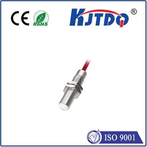
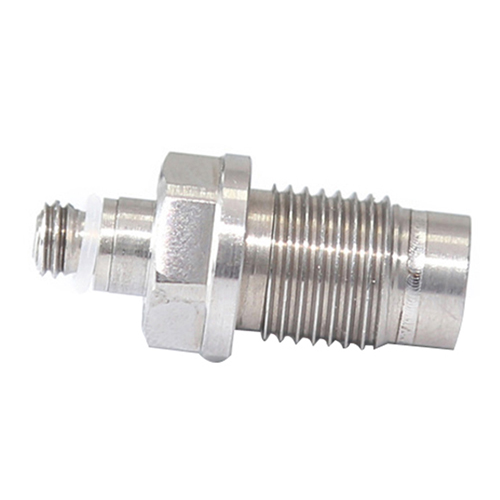
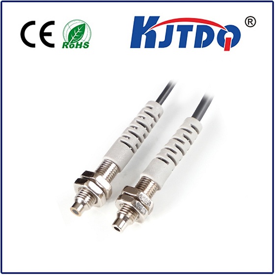
- Connector Options: Proximity sensors frequently terminate in standardized connectors like M8 (mainly for sensors) or M12 (common for both sensors and I/O blocks). Cables are often pre-fitted with these rugged, circular connectors featuring IP67 or higher ingress protection ratings, ensuring a reliable, sealed connection even in dusty or wet areas. Field-wireable connectors are also available.
- Flexibility and Bend Radius: For applications involving movement, high-flexibility cables with a specified minimum bend radius are crucial to prevent conductor fatigue and premature failure. Look for cables explicitly rated for continuous flex or torsion if needed.
Choosing the Right Cable: Key Considerations
Selecting the optimal proximity sensor cable isn’t a one-size-fits-all proposition. Carefully evaluate:
- Sensor Type & Output: Match the cable’s conductor count and specification (e.g., shielded, unshielded) to the sensor’s requirements. Analog sensors often demand higher-grade shielding than simple digital switches.
- Operating Environment: Identify the primary threats: Is it constant flexing, immersion in coolants, extreme heat/cold, UV exposure, or heavy mechanical stress? Choose the jacketing material (PUR, PVC, TPE) and shield type accordingly. Consider IP ratings for connectors.
- Electrical Noise Level: High-noise environments (near large motors, VFDs, welders) necessitate robust, continuous foil plus braid shielding for maximum EMI immunity.
- Cable Length: Longer runs increase susceptibility to signal loss and interference. Ensure the chosen cable gauge and shielding are adequate for the distance. Sometimes, using sensors with amplified outputs helps overcome long-distance limitations.
- Movement Requirements: Is the cable stationary, subject to occasional flexing, or undergoing constant motion in a cable carrier? Select cables specifically designed for the intended flex life – static, flexing, or continuous flex/torsion.
- Standards & Approvals: Check for relevant industry standards (UL, CSA, CE) or specific approvals required for your sector (e.g., food grade, flame retardant).
Installation Best Practices: Protecting Your Investment
Even the best cable can fail prematurely if installed incorrectly:
- Avoid Over-Tightening: Secure cables snugly with clamps or cable ties, but never crush the cable jacket or shield, as this can damage conductors and impair shielding effectiveness.
- Respect the Bend Radius: Never bend the cable tighter than its specified minimum bend radius, especially near connectors, to prevent internal damage.
- Proper Grounding: Ensure the cable shield is correctly and consistently grounded only at the controller end following manufacturer guidelines. Grounding at both ends can create ground loops, introducing noise.
- Route Away from Noise Sources: Keep proximity sensor cables separated from high-voltage power lines, motor leads, and other significant noise generators whenever possible. Cross them at 90 degrees if paths must intersect.
- Strain Relief: Use appropriate strain relief glands or connectors at termination points to prevent pulling force from transferring to the electrical connections inside the sensor or control cabinet.
- Regular Inspection: Periodically check cables for signs of wear, abrasion, chemical damage, or kinks. Proactive replacement is cheaper than unexpected downtime.
The Unseen Foundation of Reliable Automation
While proximity sensors grab the spotlight for detecting objects, the proximity sensor cable is the unsung hero working tirelessly in the background. Choosing the right cable and installing it correctly is not just an afterthought; it’s a fundamental investment in the reliability, accuracy, and longevity of your entire sensing system. A high-quality, appropriately specified cable ensures that the critical data generated at the sensor face travels faithfully to the control system, enabling precise automation, enhanced safety, and smooth operational flow. In the complex symphony of modern technology, the proximity sensor cable plays an indispensable, albeit silent, part.