датчик приближения pnp - nc
- time:2025-09-06 05:40:35
- Нажмите:0
The Reliable Watchdog: Unpacking PNP NC Proximity Sensors for Industrial Sensing
In the precise, high-stakes world of industrial automation, reliable sensing isn’t just convenient – it’s critical. Machines need eyes that never blink, confirming the presence or absence of parts, controlling movement, and safeguarding processes. Among the diverse array of sensing solutions, the PNP NC proximity sensor stands out for its unique operation and inherent safety benefits. Understanding its function is key to choosing the right sensor for applications where downtime or error carries real costs.
So, what exactly is a PNP NC proximity sensor? Let’s break it down:
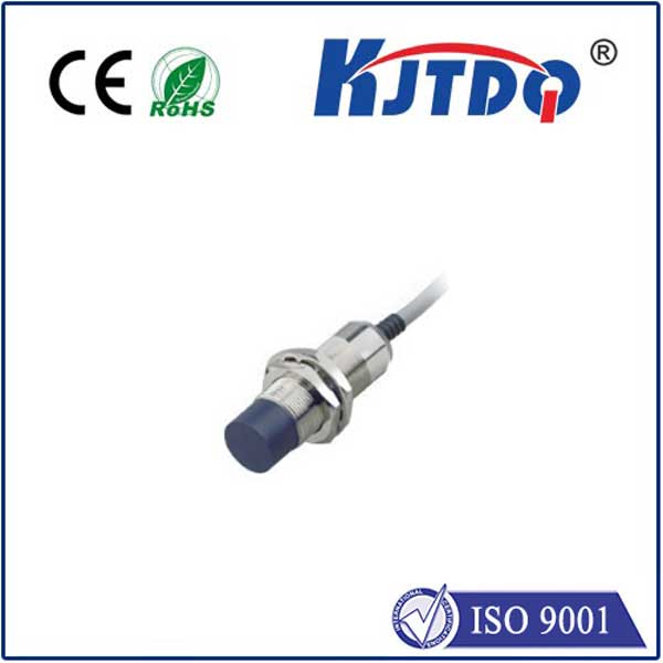
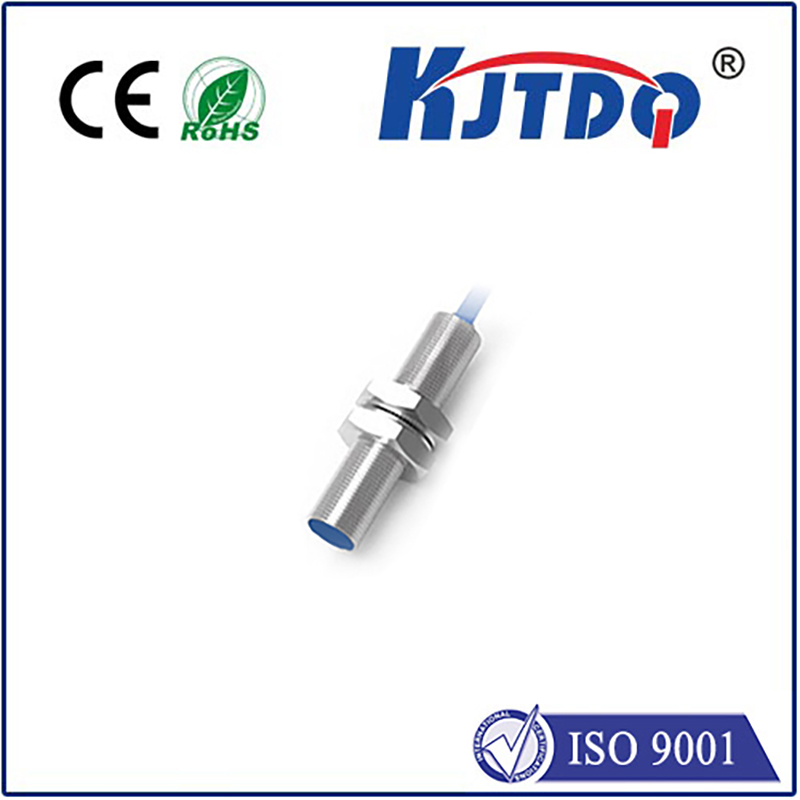
- Proximity Sensor: This is the core technology. It detects the presence or absence of a metallic object (usually ferrous metals like steel or iron, though specific types detect non-ferrous metals too) without physical contact. It achieves this through an electromagnetic field. When a target object enters this field, it causes a detectable change – eddy currents are induced in the metal, altering the sensor’s internal oscillator. This change triggers the sensor’s output circuitry.
- NC (Normally Closed): This defines the default electrical state of the sensor’s output. Normally Closed means that when the sensor is powered on but not detecting a target object, its output circuit is closed. Think of it like a switch that’s naturally “on” (conducting current) when idle. When the sensor does detect the target object within its sensing range, it opens this circuit, turning the output signal “off”.
- PNP (Positive-Negative-Positive): This specifies the type of transistor output the sensor uses and dictates how current flows. A PNP sensor has three wires: typically Brown (+V supply), Blue (0V/GND), and Black (Output). When the sensor’s output is active (in the NC case, this means no target is present), the PNP transistor switches on. This connects the Black output wire internally to the positive supply voltage (Brown). Essentially, the sensor sources current from its output to the connected load (like a PLC input module). When the output is inactive (target detected for an NC sensor), the PNP transistor switches off, and the output line is no longer connected to the positive supply – effectively becoming an open circuit.
Putting it Together: The PNP NC Sensor in Action

Imagine a safety gate on a machine. You want the machine to operate only when the gate is securely closed. A PNP NC sensor mounted to detect the gate latch in the closed position would be ideal:
- Gate OPEN (Target NOT Present - Idle State): The NC sensor’s output is active. The internal PNP transistor is switched ON, connecting the Black output wire to +V. This sourced positive voltage signal is sent to the PLC’s input, signaling “Gate Open” (or “Run Command Blocked”).
- Gate CLOSED (Target PRESENT - Detected State): The NC sensor opens its output circuit. The PNP transistor switches OFF. The Black output wire is disconnected from +V. The PLC input no longer receives the positive voltage signal, interpreting this as “Gate Closed” (or “Run Command Permitted”).
Why Choose the PNP + NC Combination? Key Advantages
- Intrinsic Fail-Safe Operation: This is the most significant advantage, especially for safety applications. If the sensor fails – due to a broken wire, loss of power, or internal component failure – the NC circuit opens. For the gate example above, this mimics the state where the gate is open. The system interprets this as an unsafe condition and prevents the machine from starting. It fails in the safe state. This is crucial for applications like emergency stop monitoring, guarding, or critical position verification. The inherent “failsafe” nature of NC contacts is highly prized in industrial safety standards.
- Understanding “No Target” vs. Failure: With an NC sensor, the absence of a signal (0V at the PLC input) can distinctly indicate either the desired detection state (target present) or a fault (sensor wire broken, no power). While this requires careful circuit design (often incorporating pull-down resistors at the PLC input module or using dual-channel safety circuits), it provides a clear indication when something is wrong. With a Normally Open (NO) sensor, a “no signal” state could ambiguously mean either “no target” or a sensor failure, which might go unnoticed.
- Suitability for Common PLC Sinking Inputs: Many PLCs have input modules configured as “sinking” inputs. This means the PLC input effectively connects to 0V/GND internally, expecting the sensor to provide the positive voltage when active. The ПНП sensor’s sourcing output (providing +V when active) is perfectly matched to drive sinking PLC inputs. The PNP NC sensor will provide the required +V signal when not detecting (its active state), perfectly compatible with the sinking input expecting that voltage.
- Clear Status Indication: The clear distinction between an active output (voltage present, indicating “no target” for NC) and an inactive output (no voltage, indicating “target present” or “fault”) can simplify logic design and diagnostics.
Ideal Applications for PNP NC Proximity Sensors
Their unique behavior makes them particularly well-suited for scenarios demanding high reliability and inherent safety:
- Safety Interlocking: Machine guarding (gates, doors, light curtains), emergency stop verification.
- Presence Verification for Critical Operations: Ensuring a part is in place before a machining operation begins, confirming a clamp is closed before welding.
- End-of-Travel Detection (Fail-Safe Mode): Verifying a cylinder is fully retracted (especially if this position is critical for safety before the next cycle starts).
- Fault Detection Circuits: Where the loss of signal from a sensor must trigger an alarm or shutdown.
- Monitoring Run States: Checking if a motor or fan has stopped spinning unexpectedly (a target on the shaft is no longer moving past the sensor).
Wiring Considerations
- Three Wires: Brown (+V Supply), Blue (0V/GND), Black (Sourcing Output).
- Load Connection: Connect the load (PLC input) between the Black (Output) wire and Blue (0V/GND). When the PNP NC sensor is active (no target), it sources +V to the PLC input via the Black wire. When inactive (target detected or fault), it stops sourcing, and the voltage at the PLC input drops to 0V (assuming a pull-down resistor is present on the PLC card).
- Fusing/Protection: Always include appropriate fusing on the supply line (Brown) to protect the sensor and wiring.
In the intricate dance of automated systems, the PNP NC proximity sensor plays a vital role as a dependable sentinel. Its normally closed configuration offers a crucial layer of fail-safe security, ensuring that system malfunctions default to a safe condition. The ПНП output provides efficient compatibility with common control hardware. By understanding the distinct operation – sourcing positive voltage when idle (no target) and interrupting that source upon detection or failure – engineers can leverage these sensors to build robust, safe, and highly reliable automation solutions. When your application demands certainty and prioritizes safety, the PNP NC proximity

