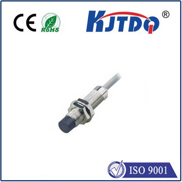
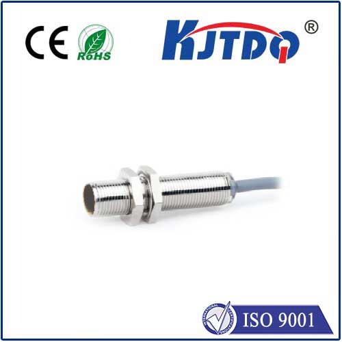
proximity sensor pcb board
- time:2025-09-06 01:51:43
- Нажмите:0
The Unsung Hero Inside: Demystifying the Proximity Sensor PCB Board
Have you ever marveled at your phone screen automatically dimming when held to your ear, or a faucet magically turning on with a wave of your hand? These seemingly effortless interactions are powered by a tiny but crucial component: the датчик приближения. And at the very heart of this sensor lies its brain and nervous system – the meticulously designed proximity sensor PCB board. This unassuming piece of electronics is the silent orchestrator, transforming simple detection into actionable intelligence.
Understanding the Core: What is a Proximity Sensor PCB?
At its essence, a proximity sensor detects the presence or absence of an object within a defined range without physical contact. Common types include IR (Infrared), Ultrasonic, Inductive (for metals), and Capacitive sensors. The proximity sensor PCB is the dedicated printed circuit board engineered specifically to support and enable the chosen sensor technology. It’s far more than just a mounting platform; it’s the integrated control center where detection, signal processing, and communication happen.
The Critical Functions of the Proximity Sensor Circuit Board
The PCB serves multiple indispensable roles:

- Component Mounting Hub: It provides the physical foundation and electrical connections for the core sensing element (like an IR LED and photodiode, or an ultrasonic transducer), the microcontroller (MCU), signal conditioning circuits, power regulation components, and output drivers.
- Signal Generation & Reception: For active sensors (like IR or Ultrasonic), the PCB generates the emission signal (e.g., modulating the IR LED or driving the ultrasonic transmitter) and provides the pathway for the returning signal (reflected IR light, ultrasonic echo) to reach the receiver circuitry.
- Signal Conditioning & Amplification: Raw signals from the sensor element are often weak and noisy. The proximity sensor circuit board houses critical components like operational amplifiers (op-amps), filters (to remove interference), and gain stages to boost the signal to a level usable by the MCU.
- Processing & Interpretation: The microcontroller embedded on the PCB is the intelligence core. It runs sophisticated algorithms to analyze the conditioned signal. This could involve measuring the time-of-flight for ultrasonic sensors, interpreting the change in light intensity for IR sensors, or detecting minute changes in capacitance for capacitive sensors. It distinguishes real presence from ambient noise or false triggers.
- Decision Making & Output: Based on the processed data, the MCU decides if an object is detected within the sensor’s range. It then triggers the designated output signal – this could be a simple digital on/off signal, a PWM output, or data sent via protocols like I2C or SPI to a main system controller. This output is what drives the action, like silencing a phone or activating a solenoid valve.
- Power Management: The PCB efficiently distributes and regulates the required voltages (often converting higher system voltages down to the low levels needed by sensitive sensor components and the MCU).
Key Components Found on a Proximity Sensor Circuit Board
A typical proximity sensor PCB board integrates several key components:
- Sensor Element(s): IR LED & Photodiode Pair, Ultrasonic Transducer, Capacitive Sensing Pad/Electrode, Inductive Coil.
- Microcontroller (MCU): The “brain” running detection algorithms.
- Signal Conditioning ICs: Op-amps, comparators, filters (active or passive).
- Oscillators/Clock Circuits: Required for signal modulation (especially IR) or MCU timing.
- Voltage Regulator: Provides stable, clean power to the sensitive analog circuits and digital logic.
- Passive Components: Precision resistors and capacitors are crucial for setting bias points, gain levels (in amplifiers), filter characteristics (cutoff frequencies), and timing circuits.
- Output Driver Circuit: Transistors or dedicated ICs to provide sufficient current/signal strength for the interface (e.g., driving an optocoupler, or a logic level output).
- Interface Connectors/Headers: For power input, ground, and communication/output signals.
Designing the Proximity Sensor PCB: Overcoming Challenges
Creating an effective proximity sensor PCB involves navigating specific design complexities:
- Minimizing Noise & Interference: Sensor signals are often microvolts or microwatts. The PCB layout must be carefully designed to shield these sensitive analog traces from digital noise radiating from the MCU or power supply. Ground planes, careful component placement, and strategic routing are paramount. Poor layout can lead to erratic behavior or reduced detection range.
- Optimizing Sensor Placement: The physical position of the sensor element relative to the target area and potential obstructions is critical. The PCB design must facilitate the best possible orientation for the sensor’s field of view or sensing field (e.g., ensuring an unobstructed path for IR light).
- Managing Power Consumption: Especially critical in battery-operated devices (like smartphones or wearables). The PCB design must incorporate low-power modes in the MCU and efficient power supply design to minimize quiescent current.
- Environmental Robustness: Depending on the application (industrial, automotive, outdoor), the PCB may need coatings (conformal coating) for moisture resistance, use wide temperature range components, or be designed to withstand vibration.
- Calibration & Tuning: Many proximity sensors require board-level calibration during manufacturing to account for component tolerances. This might involve laser-trimmed resistors, firmware calibration routines, or specific test points on the PCB.
Where the Magic Happens: Applications of Proximity Sensor PCBs
The proximity sensor PCB board is ubiquitous in modern technology:
- Consumer Electronics: Smartphones (screen dimming, auto-rotate disable), tablets, laptops, smartwatches (display activation).
- Home Automation & Appliances: Touchless faucets, soap dispensers, contactless light switches, robotic vacuum sensors, hands-free trash cans.
- Automotive: Occupancy detection (airbag activation logic), collision avoidance systems (parking sensors), gesture controls.
- Промышленная автоматизация: Object presence detection on conveyor belts, position sensing in machinery, machine guarding, level detection.
- Robotics: Obstacle avoidance, object detection for manipulation.
- Medical Devices: Non-contact controls on hygiene-critical equipment.
Design Considerations for Proximity Sensor Circuit Boards
For engineers developing proximity sensor PCBs, key considerations include:
- Choosing the Right Sensor Technology: Match the sensing principle (IR, Ultrasonic, Capacitive, Inductive) to the target object material, required range, operating environment, and cost constraints.
- Component Selection: Prioritize low-noise components for signal paths, low-power MCUs for battery life, and robust passives. Consider component size for miniaturization.
- Layout is King: Employ separate analog and digital ground planes, connect them at a single point. Keep high-frequency or noisy signals away from sensitive analog traces. Use short, direct paths for sensor connections. Place critical filters and amplifiers close to the sensor element. Decoupling capacitors must be placed as close as possible to IC power pins.
- Shielding: Consider using ground pours or physical shields around sensitive sensor circuits.
- Test Points: Include test points for critical signals (sensor output, amplified output, MCU input/output) to aid manufacturing testing and debugging.
- Thermal Management: Ensure components generating heat (like certain regulators or drivers) have adequate copper relief or thermal vias.
The proximity sensor PCB board is a masterpiece of miniaturized engineering, a critical yet often overlooked en

