optical interrupter sensor
- time:2025-08-15 06:05:16
- Нажмите:0
Optical Interrupter Sensors: The Unseen Engines of Precise Detection
Have you ever wondered how a printer knows exactly when a piece of paper is present, or how an automatic door safely stops before hitting an obstacle? Often, the silent hero enabling such precise, reliable detection is the optical interrupter sensor (OIS). This unassuming yet pivotal component operates on fundamental principles of light, providing contactless, high-speed sensing solutions across an astonishing array of industries. From your home printer to complex factory robots, optical interrupters ensure accuracy where it matters most. Let’s delve into the mechanics, benefits, and diverse applications of these versatile sensors.
At its Core: How an Optical Interrupter Sensor Functions
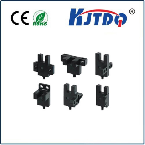
The principle is elegantly simple. An optical interrupter sensor, also commonly called a slotted optical switch or photointerrupter, consists of two core components housed facing each other across a precise air gap:
- Emitter: This side contains an infrared (IR) LED, which emits a constant, invisible beam of infrared light.
- Receiver: Positioned directly opposite the emitter is a photodetector, typically a phototransistor or photodiode, designed to be sensitive to the specific wavelength of IR light emitted by its paired LED.
The “interrupter” aspect comes into play with a physical object. When nothing blocks the gap between the emitter and receiver, the IR light beam travels unimpeded and continuously illuminates the photodetector. This causes the receiver to output a specific electrical signal state (e.g., ‘high’ or ‘on’).
Crucially, when an opaque object passes through the gap, it physically blocks the light beam. The photodetector no longer receives the IR light, causing its output signal to change state abruptly (e.g., to ‘low’ or ‘off’). This sharp transition in the output signal is the key event – the sensor has detected the presence of the interrupting object.

Key Components and Variations
While the basic emitter-receiver pair is universal, design variations cater to different needs:
- Housing: Provides mechanical alignment, protects the optical components from dust and ambient light interference, and defines the slot characteristics (width, shape).
- Slot Geometry: Determines the sensing resolution and the type of objects it can reliably detect (e.g., flags, encoder disks, teeth on a gear). Slots can be U-shaped (through-beam) or “gull-wing” gaps on surface-mount devices.
- Output Types:
- Transistor Output: The most common. The photodetector directly controls an output transistor (НС or ПНП), providing a simple on/off signal. Choose based on your circuit logic (sinking/sourcing).
- Logic Output (TTL/CMOS): Incorporates additional circuitry to provide a clean digital signal compatible with standard logic levels.
- Photodiode Output: Less common in basic interrupters; provides a small current signal requiring amplification.
- Additional Features: Some advanced models include Schmitt triggers for noise immunity, ambient light shielding, or integrated lenses for increased sensing distance within the slot.
Significant Advantages Over Alternatives
Why choose an optical interrupter sensor over other detection methods like mechanical switches or proximity sensors? Several compelling advantages drive their widespread adoption:
- Contactless Sensing: Unlike mechanical switches, there’s zero physical contact with the object being detected. This eliminates wear and tear, ensuring exceptional long-term reliability and eliminating bounce issues. Objects don’t need to be ferrous like with inductive sensors.
- High Speed: The light-based detection is extremely fast. Optical interrupters can reliably sense objects moving at very high speeds or vibrating rapidly – speeds far beyond the capability of mechanical switches.
- Precision: The detection point is defined by the narrow gap between the emitter and receiver, allowing for very high positional accuracy and repeatability. They excel at edge detection and counting.
- Environmental Resilience: Properly housed optical interrupters are highly resistant to contaminants like dust, oil, and moisture that could easily jam mechanical contacts or obscure the lens of a separate emitter/receiver reflective sensor. The integrated design minimizes alignment issues.
- Electrical Noise Immunity: As self-contained, close-coupled devices generating their own light signal (IR), they are generally less susceptible to electromagnetic interference (EMI) than some other sensor types.
Diverse Applications: Where Optical Interrupters Shine
The unique blend of contactless operation, speed, precision, and reliability makes optical interrupter sensors indispensable in countless scenarios:
- Position Sensing & Limit Switching: Detecting the presence/absence of an object or its end position. Common in printers (paper out, carriage position), copiers, vending machines (product drop detection), and CNC machines (tool or axis limits).
- Rotary Encoding: Mounting an interrupter next to a slotted disk attached to a motor shaft allows precise measurement of rotational speed, position, and direction (using multiple sensors). Vital in motor control and robotics.
- Linear Encoding: Using a sensor paired with a linear scale featuring slots or markings enables precise measurement of linear position.
- Object Counting & Flow Monitoring: Counting items on a conveyor belt (detecting gaps or flags), monitoring rotation of gears or shafts, checking web breaks in material handling.
- Level Detection: Sensing presence/absence of vials, test tubes, or materials at specific points.
- Safety Interlocks: Used as non-contact safety switches in enclosures where opening a door needs to immediately cut power to moving parts.
- Consumer Electronics: Found in appliances, 3D printers (filament runout sensors, endstop switches), and optical mice.
Choosing the Right Optical Interrupter Sensor
Selecting the optimal sensor involves considering several parameters:
- Operating Voltage: Ensure compatibility with your system voltage (e.g., 3.3V, 5V, 12V, 24V).
- Output Configuration: Select НС (sinking) or ПНП (sourcing) transistor output based on your controller’s input requirements. Confirm logic level compatibility for TTL/CMOS types.
- Slot Size: Match the gap width and depth to the size and shape of the object you need to detect. Consider the tolerance of the interrupting object.
- Sensing Resolution: For encoding tasks, ensure the slot width or disk tooth geometry is compatible with the sensor’s gap for reliable triggering.
- Response Speed/Rise/Fall Time: Critical for high-speed applications. Check the datasheet for timing specifications.
- Operating Temperature Range: Ensure suitability for the intended environment.
- Mounting: Consider PCB mount (vertical/horizontal) or chassis mount options.
Always consult the manufacturer’s detailed datasheet. It provides essential information on electrical characteristics, optical performance, mechanical dimensions, and recommended operating conditions. Consider factors like potential ambient light exposure and the mounting environment.
A Fundamental Building Block
The optical interrupter sensor exemplifies elegant engineering. By leveraging the simple interruption of a light beam, it delivers robust, contactless, and high-precision detection. Its inherent reliability and high-speed operation make it a cornerstone technology across automation, consumer electronics, industrial control, and countless other fields. Understanding its function, benefits, and selection criteria empowers engineers and designers to effectively integrate this essential component, enabling machines to perceive their world with remarkable accuracy.