Invisible electricity flows power our lives, yet understanding its consumption often remains guesswork. What if your NodeMCU could lift this veil, transforming raw current into actionable insight? Integrating a current sensor with the versatile NodeMCU (ESP8266) unlocks a world of possibilities, from safeguarding devices and optimizing energy bills to creating sophisticated home automation systems. This practical guide dives into the how and why of pairing these technologies.
Why NodeMCU for Current Sensing? The NodeMCU isn’t just another microcontroller; it’s an IoT powerhouse perfectly suited for this task. Its built-in Wi-Fi connectivity is revolutionary. Imagine your sensor readings not just displayed locally but instantly accessible globally via your smartphone dashboard or cloud platform like Blynk, ThingSpeak, or Home Assistant. The Integrated Analog-to-Digital Converter (ADC), while not perfect (typically 10-bit resolution), is fundamental for converting the sensor’s analog voltage output into a digital value the NodeMCU can process. Combine this with its low cost, ease of programming via the familiar Arduino IDE, and rich ecosystem of libraries, and you have an ideal platform for intelligent energy monitoring projects, accessible to hobbyists and professionals alike.
Choosing Your Current Sensor Companion Selecting the right sensor is critical. Here are the two most common types compatible with NodeMCU:

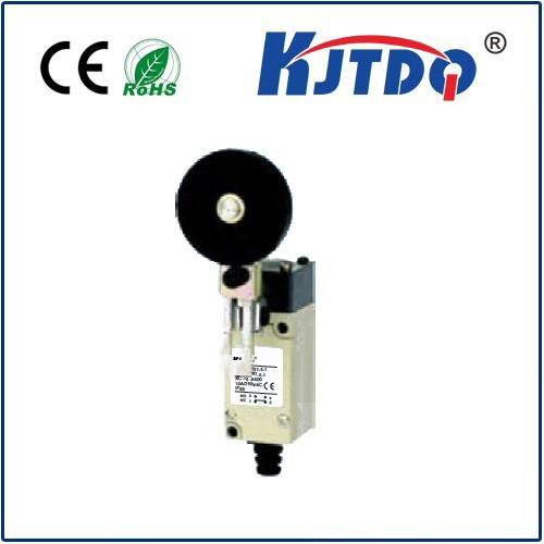
Hall-Effect Sensors (e.g., ACS712): These are incredibly popular and relatively safe for beginners. They work by detecting the magnetic field generated around a conductor carrying current. They provide galvanic isolation, meaning the high-current circuit is electrically separated from your NodeMCU’s low-voltage logic, a vital safety feature. Models like the ACS712 come in various current ranges (5A, 20A, 30A). Their output is an analog voltage centered around Vcc/2 (e.g., 2.5V) when no current flows, swinging above or below based on current direction. Their main disadvantage is the need to break the circuit to insert them in series with the load.
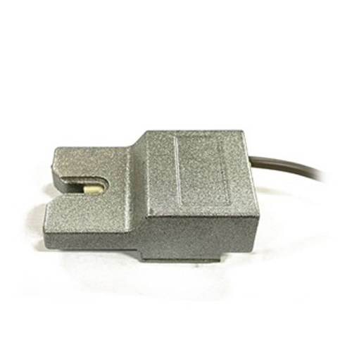
Non-Invasive Current Transformers (CT Sensors): These clamp around the insulated wire carrying current. They work based on electromagnetic induction. The CT acts as a step-down transformer, producing a smaller AC current proportional to the current flowing through the wire you’re measuring. Crucially, you NEVER break the main circuit.А.burden resistor converts this secondary current into a measurable voltage for the NodeMCU’s ADC. CT sensors are ideal for monitoring mains AC circuits safely and are commonly found in commercial energy monitors. They typically only measure AC.
Connecting the Dots: Wiring Essentials While specific pinouts vary slightly, the principle remains consistent:
The Code: Reading and Interpreting Values The magic happens in software. Here’s the essence:
analogRead(A0) function to get a raw ADC value (0-1023 for NodeMCU v3’s 10-bit ADC).sensorVoltage = (rawADC * operatingVoltage) / ADCResolution (e.g., 5.0 / 1023.0).current = (sensorVoltage - zeroVoltage) / sensitivity. Sensitivity (e.g., 0.185V/A for 20A model) is found in the datasheet.currentRMS = (sensorVoltageRMS * CT_Turns_Ratio) / Burden_Resistor. Using a proven library (like “EmonLib” for AC) is highly recommended for accuracy and handling RMS calculations.Power = Voltage * Current.Unleashing Practical Applications Armed with this setup, the applications are vast:
Essential Considerations & Safety
The NodeMCU paired with a current sensor transforms theoretical IoT into tangible, powerful energy intelligence. By understanding the core principles of sensor selection, wiring, coding, and calibration, you unlock the potential to visualize, analyze, and optimize electrical consumption like never before. What energy-saving insight will your NodeMCU reveal first?