Шаговый ограничитель
- time:2025-08-07 00:40:29
- Нажмите:0
Stepper Limit Switches: Your System’s Unsung Guardian Against Mechanical Catastrophe
Imagine your high-precision CNC router meticulously carving a complex design. Or a sophisticated robotic arm performing delicate assembly tasks. Now, picture what happens if that motion doesn’t stop when it’s supposed to. The grinding sound of metal on metal, the splintering of components, the potential for costly downtime and repairs. This is the stark reality a Шаговый ограничитель is specifically designed to prevent. Far from being a mere accessory, it’s a fundamental safety net, the critical sentinel standing guard at the physical boundaries of your stepper motor system’s movement. Its sole mission is to detect when a mechanism has reached the end of its intended travel and intervene decisively to halt motion before damage occurs.
Understanding the Core Components: Stepper Motors and Their Need for Limits
Stepper motors excel at precise positional control. They move in discrete steps, allowing controllers to track position accurately without absolute encoders, often within a closed-loop system using step count. However, this inherent advantage carries a significant vulnerability: stepper motors possess immense holding torque. Unlike a DC motor that might stall under excessive load, a stepper motor will continue trying to drive against a physical obstruction. This relentless force translates into:
- Mechanism Stress: Belts can stretch or snap, lead screws can bend or bind, gears can strip, and bearings can seize.
- Motor Strain: The motor itself overheats rapidly, potentially damaging windings or the driver circuitry.
- Positional Loss: The motor can “skip steps,” losing its known position relative to the controller’s step count, rendering the entire positioning system inaccurate.
This is precisely where the ограничительный переключатель becomes indispensable. It acts as an absolute position reference, defining the hard physical endpoints beyond which movement is forbidden.

How Stepper Limit Switches Function: Interrupting the Flow
The core principle of a stepper limit switch is elegantly simple: detect physical presence and interrupt a signal. Let’s break down the typical operational flow:
- Physical Contact or Detection: As the moving part (like a gantry carriage, print head, or actuator arm) approaches its travel limit, it physically contacts the switch’s actuator (lever, roller plunger, etc.), or passes through a non-contact sensor’s detection field (like optical or magnetic).
- Electrical State Change: This contact or detection causes the switch’s internal electrical contacts to change state. Most commonly, this is a normally open (NO) contact closing or a normally closed (NC) contact opening when activated.
- Signal to Controller: The change in the switch’s electrical state is wired directly to the stepper motor driver or the main motion controller board. This input is typically designated as a limit switch input or endstop. Crucially, the controller firmware is programmed to interpret this signal change as an immediate stop command.
- Emergency Halt: Upon receiving the activated limit switch signal, the controller takes urgent action:
- Instantly cuts power to the stepper motor coils, removing the driving force.
- Triggers an error state or fault condition within the system.
- Prevents any further commanded motion in the direction that triggered the limit until the condition is acknowledged and cleared (often requiring manual intervention or a homing sequence).
Types of Limit Switches Used with Steppers: Choosing the Right Guard
Selecting the appropriate limit switch depends on factors like required precision, environmental conditions, budget, and physical mounting constraints:
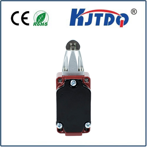
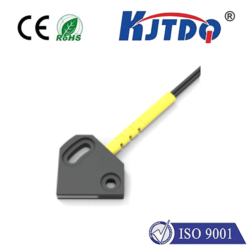
- Mechanical Switches: The most common and cost-effective type. They feature a physical actuator arm/lever/roller that must be depressed or triggered by the machine part.
- Pros: Simple, inexpensive, robust for many applications, easy to wire and understand.
- Cons: Prone to wear over time, potentially susceptible to vibration (bouncing contacts), debounce delay needs consideration, physical contact required which might not suit fragile components. Switch bounce can cause multiple rapid on/off transitions, requiring debounce circuitry or firmware filtering in the controller.
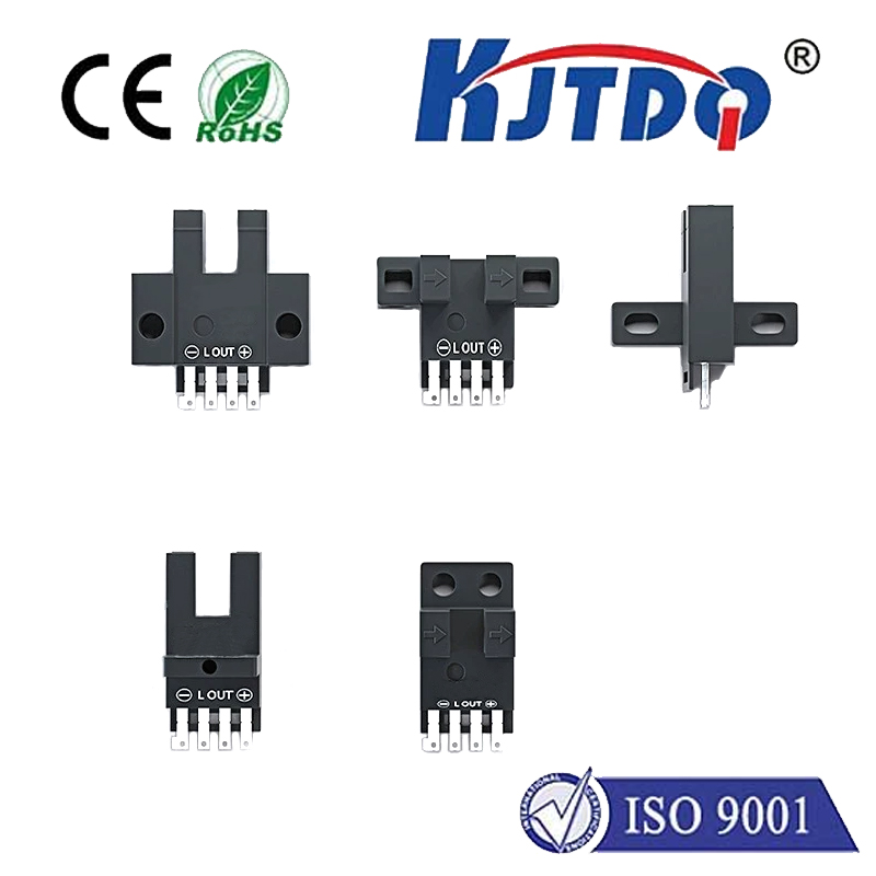
- Optical Switches (Opto-Interrupters): Use an infrared (IR) LED and a phototransistor/photodiode. An object interrupts the light beam, changing the output state.
- Pros: Very fast, no physical contact (no wear), excellent repeatability, immune to vibration.
- Cons: Can be more expensive, sensitive to dust/dirt/cobwebs blocking the beam, ambient light interference (can be mitigated with modulation), requires precise alignment.
- Hall Effect Switches: Detect the presence of a magnetic field. A small magnet is mounted on the moving part; when it passes close to the stationary Hall sensor, the switch triggers.
- Pros: Non-contact, fast, long lifespan, immune to dust/dirt (unless ferrous), robust.
- Cons: Requires a magnet on the moving component, sensitive to external magnetic fields, positioning accuracy might be slightly less precise than optical.
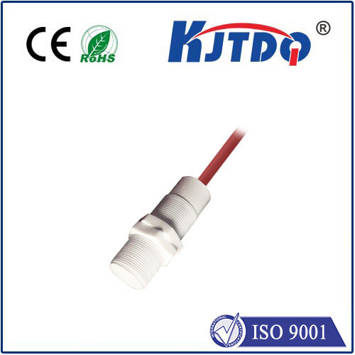
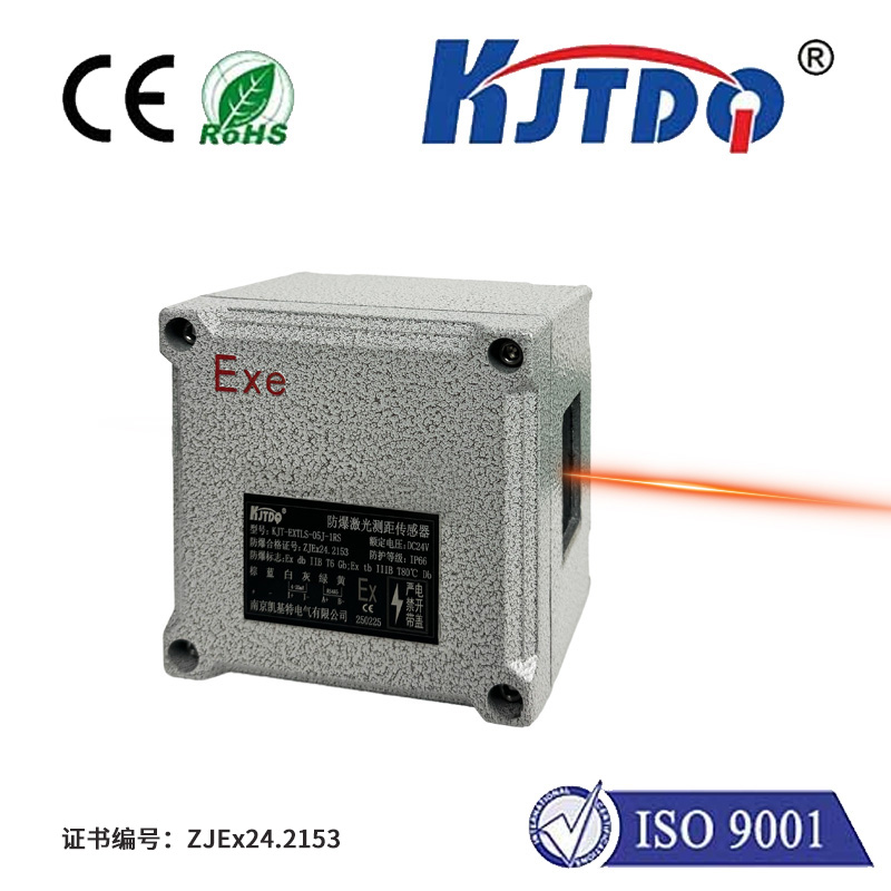
- Proximity Sensors (Inductive/Capacitive): Detect the presence of metallic (inductive) or any material (capacitive) objects without contact.
- Pros: Non-contact, suitable for harsh environments (dust, moisture), robust packaging options.
- Cons: Typically more expensive, greater sensing distance might require careful setup to avoid false triggers, require specific target materials (inductive).
Beyond Just Stops: Homing and Calibration
While overtravel protection is the primary safety function, stepper limit switches play another vital role: homing. At startup, most CNC machines, 3D printers, and robotic systems need to establish a known reference point (“home” or “zero” position). This is achieved by:
- Slowly moving an axis in a designated direction until it activates its home limit switch.
- The precise moment the switch triggers marks the absolute physical zero point for that axis within the machine’s coordinate system.
- The controller then uses this known location to accurately position the tool or end-effector for all subsequent operations. The accuracy and repeatability of the homing switch directly impact the overall positioning accuracy of the entire machine.
Implementing Stepper Limit Switches Effectively: Best Practices
For reliable operation, consider these key points:
- Strategic Placement: Position switches so they trigger just before any mechanical interference occurs. Include some margin of safety.
- Robust Mounting: Securely fasten the switch and its actuator/target to prevent shifting due to vibration or accidental bumps, which could lead to false triggers or missed triggers.
- Wiring Integrity: Use shielded cable if noise is a concern, especially in environments with variable frequency drives (VFDs) or strong electromagnetic interference (EMI). Secure connections to prevent shorts or opens. Connect switches appropriately based on the controller’s requirements (e.g., NO vs NC configuration). Understanding whether your controller expects an active-low or active-high signal for a limit trigger is paramount.
- Firmware Configuration: Correctly set the endstop logic (e.g., active high/low) in the machine’s firmware (like GRBL, Marlin, Mach3). Configure reliable debounce settings if using mechanical switches.
- Regular Maintenance: Periodically check switch operation manually to ensure they trigger reliably and haven’t become loose or damaged. Clean optical sensors.
**The Critical Importance: Why You Can’t Afford to