Ever experienced that gut-sinking moment when your CNC machine head slams unexpectedly into the frame? Or worse, keeps pushing beyond its physical boundaries, threatening expensive damage? This nightmare scenario is precisely what GRBL limit switches are designed to prevent. Understanding the GRBL limit switch status is not just technical jargon; it’s fundamental to safe, reliable, and efficient CNC operation. It’s the critical communication channel between your machine’s physical safety mechanisms and the GRBL controller, telling you exactly what’s happening at the boundaries.
What Are Limit Switches and Why Does GRBL Need Them?
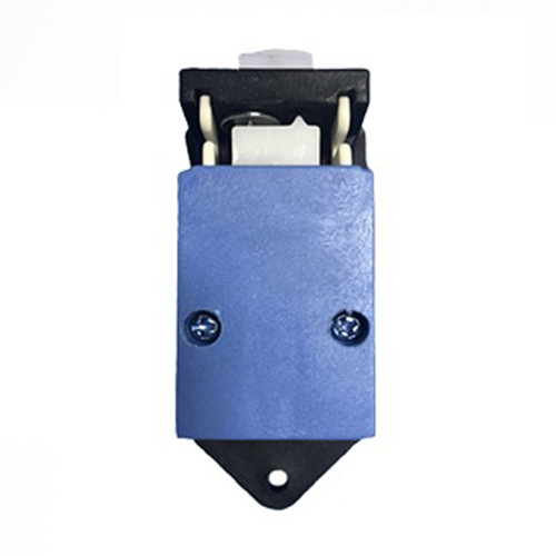
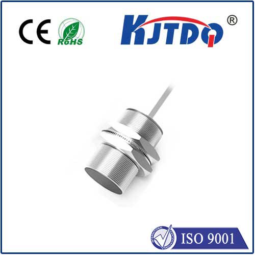
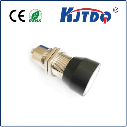
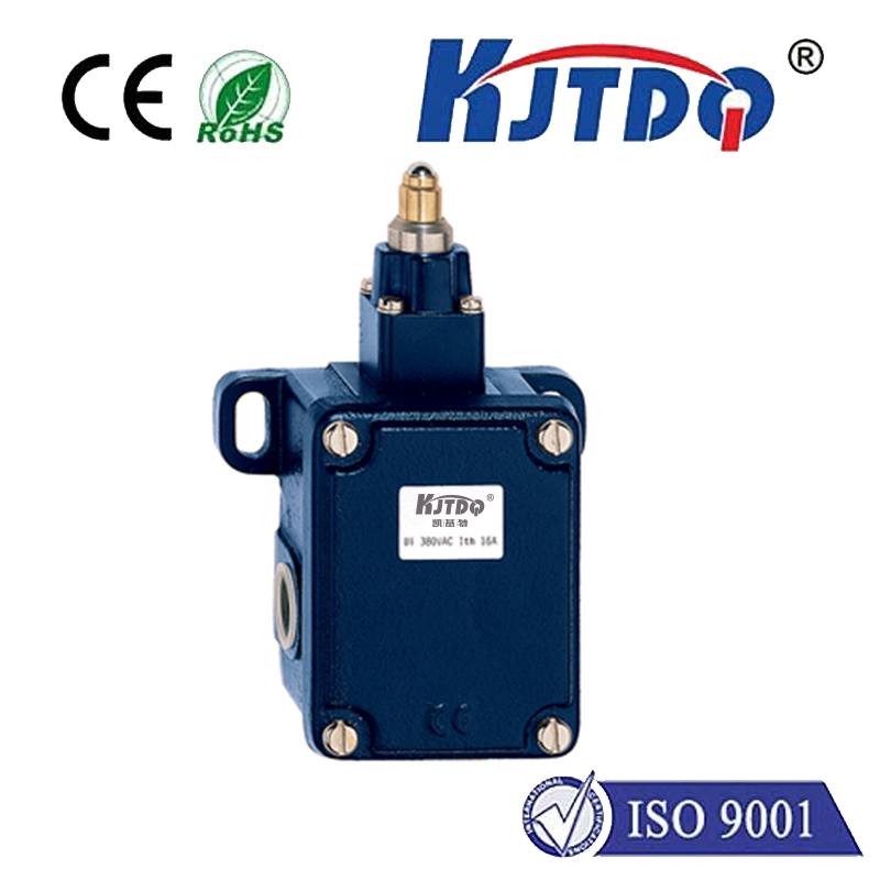
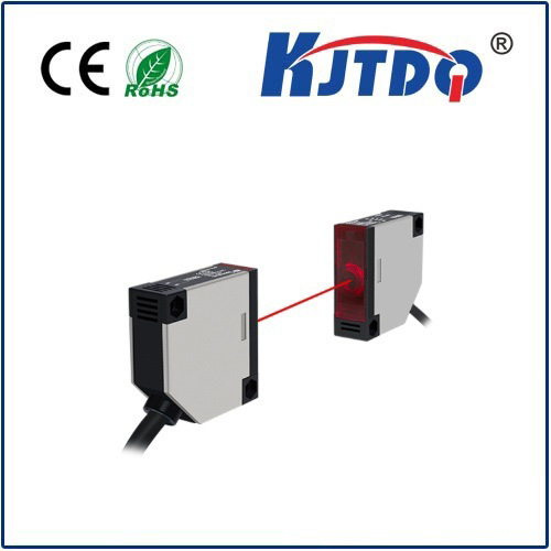
Limit switches are simple electromechanical or proximity sensors positioned strategically at the physical ends of each axis on your CNC machine (X, Y, Z, and sometimes more). Their sole purpose is to detect when the machine’s moving parts reach a predefined boundary. GRBL leverages these switches for two primary safety functions:

ALARM:1). It stops all motion by cutting power to the motors (hard stop). Hard limits are your last line of defense against catastrophic crashes.$H), GRBL deliberately drives each axis towards its limit switch. Upon triggering, GRBL precisely backs off, finds the switch’s precise repeatable point (often using a two-stage approach), and sets that location as the machine’s absolute zero position (Machine Coordinates = 0). Accurate homing is crucial for consistent part positioning.Deciphering the GRBL Limit Switch Status
So, how does GRBL tell you what these vital switches are doing? GRBL provides real-time feedback through several methods:
? command): Sending a ? (query) to GRBL returns a comprehensive status report. A key part of this report is the Pn: field, where n represents the pin status bitmask. While interpreting the raw bitmask requires consulting GRBL’s documentation for your specific pin mapping, the status report clearly indicates ALARM:1 when a hard limit is triggered, immediately alerting you to the problem. Homing cycle progress (Idle, Run, Домашняя страница) is also shown here.$H (homing cycle), GRBL outputs detailed messages:[MSG:Reset to continue] might indicate a limit is already triggered before starting.[MSG:Cycle Start] confirms homing initiated.[MSG:Searching for X, Y, Z Limit :X] show which axis is actively seeking its switch.[MSG:Found X, Y, Z Limit :X] confirms successful switch contact.[MSG:Home X] indicates axis zero has been set after the second touch-off.ALARM:2 signifies a homing failure – usually because a switch wasn’t found within the configured search distance ($22).Troubleshooting Common Limit Switch Status Issues
A non-functional or falsely triggered limit switch brings your machine to a halt. Understanding the status helps diagnose:
ALARM:1: This is a hard limit triggered. Check:ALARM:2): GRBL couldn’t find the switch. Check:$22) large enough for the machine to physically reach the switch? ($22=100.0 is a common large starting value).$23) set correctly? ($23=0 usually homes towards positive switches, $23=1 towards negative).$5 setting in GRBL matches this. $5=0 enables limit pins with NO switch logic (common), $5=1 enables NC logic. A mismatch causes constant alarms or failure to detect triggers. Also check for short circuits or grounding issues.Configuring and Optimizing Limit Switch Behavior in GRBL
Several GRBL settings ($$ to list) directly impact limit switches:
$5 - Limit Pins Enable / Invert: As mentioned, $5=0 (default) enables pins with NO switch logic. $5=1 enables NC logic. Changing this incorrectly will cause major issues!$20 - Soft Limits Enable: $20=1 activates soft limits only after homing. Soft limits use the machine coordinates and $130/$131/$132 (max travel) to halt programs before a physical crash, but they do not stop manual jogging beyond limits – that’s the job of hard limits. Soft limits require homing and are complementary, not a replacement for hard limits.$21 - Hard Limits Enable: $21=1 (highly recommended) enables hard limits. Disable ($21=0) only during careful setup/troubleshooting.$22 - Homing Cycle Enable: $22=1 enables the homing cycle ($H command). Must be enabled to use homing switches.$23 - Homing Direction In