Переключатель торцевой остановки 3D - принтера
- time:2025-08-03 01:10:47
- Нажмите:0
The Unsung Hero of Perfect Prints: Understanding Your 3D Printer End Stop Switch
(Article Title)
That sickening CRUNCH. You hear it just before your 3D printer jolts to an unnatural halt, layers misaligned, filament grinding. Or maybe it’s the opposite: your print head drifts lazily past the build plate, its first layer destined for thin air. More often than not, the culprit behind these frustrating failures isn’t your slicing software or even the filament – it’s a tiny, often overlooked component: the end stop switch.

Often called a limit switch or homing switch, the 3D printer end stop switch is a fundamental safety and calibration device. Think of it as the traffic light at every intersection of your printer’s movement. Its sole, critical job is to tell the printer’s brain (the control board) precisely when a moving part (like the print head, build plate, or gantry) has reached the absolute end of its designated travel along an axis – X, Y, or Z. Without these essential sensors, your printer would literally crash into its own frame, causing damage, failed prints, and immense frustration.
Why End Stops Are Non-Negotiable
Imagine trying to park a car blindfolded without hitting the garage wall. That’s essentially what a 3D printer attempts without functional end stops. Here’s why they are indispensable:
- Establishing “Home”: Every print job begins with a homing sequence. The printer rapidly moves each axis towards its end stop. When the switch activates (is “triggered”), the printer instantly knows, “This is the exact starting point (0,0,0 or Home position) for this axis.” This calibration is crucial for the printer to place the nozzle accurately anywhere on the build plate.
- Preventing Physical Damage: The most vital function. End stops physically prevent the stepper motors from forcing components like the hot end or build plate beyond their mechanical limits. They act as an electronic bumper, stopping motion before destructive collisions occur. Forcing motors beyond their limits can strip belts, bend rods, damage motors, or break mounts.
- Ensuring Print Accuracy & Consistency: If the printer doesn’t know where “home” is reliably, the intricate movements calculated by the slicer become meaningless. A malfunctioning end stop leads to layer shifting, poor bed adhesion, misaligned features, or prints consistently drifting off-center – even if everything else seems perfect.
The Three Faces of Precision: Types of 3D Printer End Stops
While their function is universal, the technology behind end stop switches varies, each with distinct advantages and drawbacks:
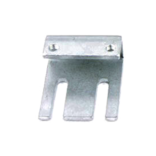
- Mechanical (Microswitch):
- How it Works: The most common and recognizable type. Features a small physical lever or button. When the moving part (like the X-carriage) touches this lever, it physically presses the internal switch mechanism, completing an electrical circuit and sending the “STOP” signal.
- Pros: Inexpensive, reliable, robust, and simple to troubleshoot. The physical “click” provides audible confirmation of triggering.
- Cons: Prone to physical wear over time as the lever is repeatedly actuated. Can potentially bounce mechanically (send multiple rapid signals instead of one clean one), though firmware often includes debounce settings to compensate. Lever position needs careful adjustment. Vulnerable to physical obstruction or damage.
- Optical (Opto-Endstop):
- How it Works: Utilizes an infrared LED and a phototransistor/sensor housed on opposite sides of a slot. When the moving part slides a small flag (vane) into this slot, it blocks the infrared light beam. The sensor detects this interruption and signals the controller.
- Pros: Non-contact operation eliminates mechanical wear. Highly precise and repeatable triggering point. No physical pressure needed, making them ideal for very lightweight carriages. Immune to dust inside the sensor slot.
- Cons: Generally more expensive than mechanical switches. Sensitive to ambient light interference (though good designs shield against this). Dust or debris on the sensor or flag can block the beam and cause false triggers or prevent triggering. Requires precise flag alignment.
- Magnetic (Hall Effect Sensor):
- How it Works: Uses a Hall effect sensor that detects the presence (or absence) of a magnetic field. A small magnet is mounted on the moving part. When the magnet comes very close to the stationary sensor, the sensor detects the change in the magnetic field and triggers.
- Pros: Truly contactless and silent operation. Virtually immune to dust, debris, and moisture affecting the sensing mechanism. Excellent long-term reliability with no moving parts to wear out.
- Cons: Typically the most expensive type. Requires careful alignment between the sensor and magnet. Triggering distance is very small and fixed. Susceptible to interference from other strong magnetic fields nearby.
The Silent (or Not-So-Silent) Cry for Help: Troubleshooting End Stop Issues
A failing or misconfigured end stop switch manifests in clear, often alarming, ways:
- Printer Crashing into the Frame: The most obvious sign. The axis motor keeps driving even after it should have stopped, resulting in grinding noises and potential damage. Immediately power off the printer if this happens!
- Failed Homing: The printer attempts to home but stops with an error message like “Homing failed,” “Axis Min/Max Error,” or “Printer halted, kill() called!”.
- Inconsistent “Home” Position: Prints start in slightly different locations each time, leading to inconsistent first layers or parts being printed off the bed.
- Axis Unable to Move: If an end stop is permanently triggered (e.g., switch stuck closed, debris blocking an optical sensor, magnet stuck near Hall sensor), the printer thinks that axis is already at its limit and refuses to move away from the end stop.
Common Culprits & Fixes
- Misalignment: The most frequent issue. The physical switch lever, optical flag, or magnet isn’t being hit/interrupted reliably during homing. Solution: Carefully adjust the position of the switch body or the trigger (flag/magnet) on the moving part. Consult your printer’s manual. Double-check grub screws holding components!
- Mechanical Failure: A microswitch lever breaks, the internal contacts wear out, or the switch body becomes loose. Solution: Replace the microswitch. They are standard, inexpensive components.
- Wiring Issues: Loose connector at the switch or mainboard, crimped wire, or broken solder joint. Solution: Visually inspect wires; gently wiggle connectors during homing to see if it intermittently works; reseat connectors; replace damaged wires. Ensure power is off during inspection.
- Optical Sensor Blocked: Dust or stray filament obstructing the IR beam path. Solution: Carefully clean the sensor slot and the trigger flag with compressed air or a soft brush.
- Firmware Configuration: Incorrect end stop logic settings in the printer’s firmware (e.g., setting as normally open vs normally closed incorrectly). Solution: Requires accessing firmware configuration (like Marlin) and verifying the `X