Схема выключателя предельного положения исполнительного устройства
- time:2025-08-01 11:25:12
- Нажмите:0
Actuator Limit Switch Schematics: Your Blueprint for Motion Control Safety
Imagine a powerful hydraulic arm lifting a massive load, or a robotic actuator precisely positioning a component. Now, imagine if that movement had no defined stopping point. The potential for damage, failure, or even catastrophic accident is immense. This is where the unassuming yet utterly critical actuator limit switch comes into play, silently acting as the guardian of travel boundaries. But understanding how these essential components function within a larger system requires peering into the schematic – the universal language of electrical and control design. Demystifying actuator limit switch schematics is key to designing, installing, maintaining, and troubleshooting safe and reliable motion control systems.
The Role of the Limit Switch: Defining the Edges
At its core, an actuator limit switch is a sensor. Its primary function is to detect when an actuator (linear or rotary) has reached a predetermined physical position at either the fully extended (outstroke) or fully retracted (instroke) end of its travel. Upon detection, it sends a signal – typically by opening or closing an electrical contact – back to the control system. This signal is the fundamental input that tells the controller, “Stop! This is as far as it should go.”
The implications are profound:

- Safety: Prevents over-travel that could cause mechanical damage to the actuator itself, the driven load, or surrounding equipment.
- Process Control: Ensures the actuator moves only within its designed operational range, guaranteeing repeatability and accuracy.
- Interlocking: Provides essential interlock signals, perhaps preventing another machine function from starting until the actuator is confirmed to be in a “home” or “safe” position.
- Operator Protection: Creates a fundamental layer of safety preventing unintended actuator movement beyond safe zones.
Decoding the Schematic: Symbols and Conventions
The schematic diagram visually represents the electrical and logical relationships within a circuit. For actuator limit switches, standardized symbols are used globally, making these diagrams universally interpretable by engineers and technicians.
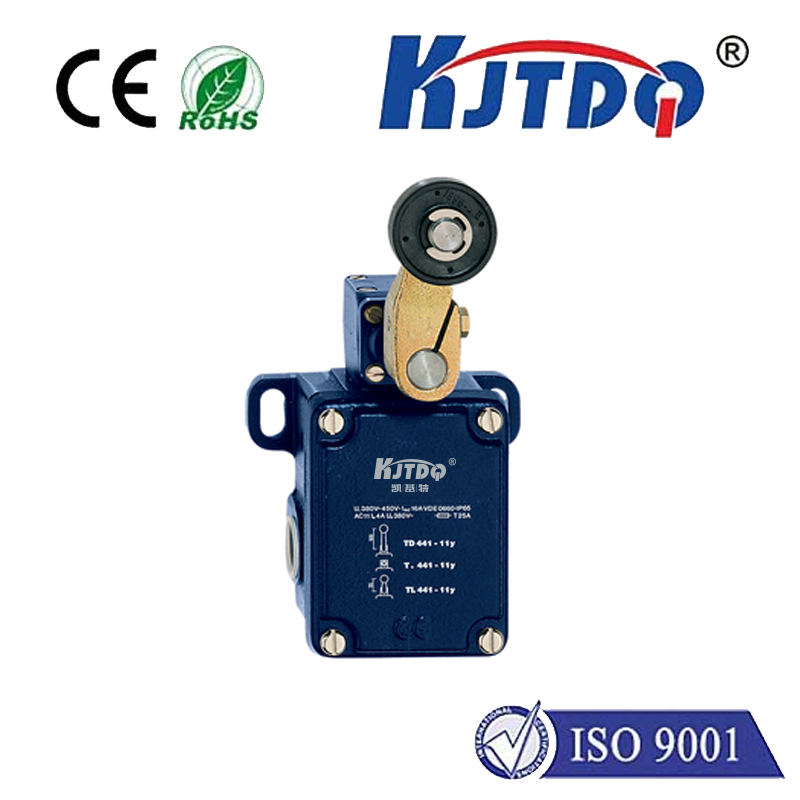
- The Basic Switch Symbol: A limit switch is most commonly depicted as a simple switch symbol (like a SPST - Single Pole, Single Throw switch) but with a distinctive actuator lever attached. This lever symbol represents the physical mechanism (roller plunger, whisker, etc.) that gets depressed or activated by the moving part of the actuator.
- Normally Open (NO) vs. Normally Closed (NC): This is crucial! In its rest state (actuator not touching it), a limit switch contact is either:
- Normally Open (NO): Circuit is open (no current flow). Activation closes the contact. Often labeled
LS-EXT-NO for an extend limit.
- Normally Closed (NC): Circuit is closed (current flows). Activation opens the contact. Often labeled
LS-RET-NC for a retract limit.
- Understanding the default state and the action upon activation is paramount for interpreting the circuit logic.
- Labeling: Schematics rely heavily on clear labels. Limit switches are typically designated with identifiers like:
LS1, LS2, etc. (Limit Switch 1, 2…)EXT-LS (Extend Limit Switch)RET-LS (Retract Limit Switch)HOME-SW (Home Position Switch)- Combination labels like
LS-RET-NC (Retract Limit Switch, Normally Closed) are highly informative.
- Connection Points: The schematic shows where the switch wires connect:
- One side typically connects to a control voltage source (e.g., +24VDC).
- The other side connects to the specific input point of a Programmable Logic Controller (PLC), motor starter coil, relay coil, or directly into a safety relay module.
- Integration with Actuator Control: The schematic reveals how the limit switch signal integrates into the wider control circuit for the actuator’s motor or solenoid valve. For example:
- An extend limit switch
Нет! contact might be wired in series with the coil of the relay responsible for supplying power for extending the actuator. When the extend limit is hit, the contact closes, but if wired as a stop signal, this contact might actually be used to interrupt the extend command circuit elsewhere.
- Safety Circuits: Limit switches are often integral parts of safety circuits. Their signals might feed directly into safety relays or Safety PLCs, which are designed with redundant channels and self-monitoring to ensure a high level of safety integrity (SIL or PL rated). A schematic shows these critical safety interconnections clearly.
Schematic Design Principles for Limit Switches
A well-designed Схема выключателя предельного положения исполнительного устройства follows key principles:
- Clarity and Consistency: Symbols and labeling must be standardized and unambiguous.
- Function Over Form: The schematic must accurately reflect the intended logic of the safety and control system, not just the physical wiring.
- Safety Circuit Separation: Critical safety limit switches should be shown integrated within clearly demarcated safety-related control circuits, often distinguished from standard control circuits by color-coding or specific symbols.
- Fail-Safe Considerations: Schematics often depict how the system behaves on switch failure. Using NC contacts for critical stop functions is a common fail-safe practice, as a broken wire or switch failure defaults to the “open circuit = stop” state. This principle should be evident in the diagram’s logic flow.
- Auxiliary Contacts/Indication: Schematics might include connections for indicator lamps (e.g., “At Extend Limit”) or auxiliary contacts used for signaling to other parts of the control system.
Common Applications Illustrated in Schematics
- Linear Actuators: The schematic shows limit switches positioned at each end of the cylinder’s travel path. Actuation typically occurs when a target block on the piston rod depresses the switch lever.
- Rotary Actuators: Schematics depict switches triggered by a cam attached to the rotating shaft or by the actuator body itself reaching a lug. Rotary switches often handle both limits with one unit.
- Complex Machinery: Schematics for machines with multiple actuators will show the network of limit switches, revealing their interrelationships and how the status of one actuator (e.g., “Cylinder A Retracted”) enables or disables the movement of another (e.g., “Cylinder B Extend”).
Installation and Troubleshooting Through the Schematic
The schematic is the indispensable reference point for both installing and diagnosing issues with actuator limit switches:
- Installation: Technicians use the schematic to verify:
- Correct physical switch type (NO/NC) is mounted.
- Wiring connections match the diagram (which wire goes to which terminal).
- The switch is positioned correctly to be reliably actuated at the precise end of travel.
- Troubleshooting: When an actuator fails to stop, or won’t move in a desired direction, the schematic guides the troubleshooting process:
- Verify Signal: Use a multimeter to check if the switch is changing state (open/close) when manually actuated. Does this match the schematic’s indicated behavior?
- Circuit Continuity: Trace the circuit path shown in the schematic. Is there voltage where expected? Is the signal reaching the PLC input or relay coil?
- Identify Fault Points: The schematic helps isolate the problem – is it the switch itself, the wiring, the input module, or the control logic programmed in the PLC? Misinterpretation of the intended NO/NC logic in the schematic versus the physical switch wiring is a frequent culprit.
Beyond the Basics: Advanced Depictions
While simple SPST representations are common, schematics may also detail more complex switches:
- Double-Break Contacts: Shown with two sets of contact symbols per pole, indicating higher reliability/current