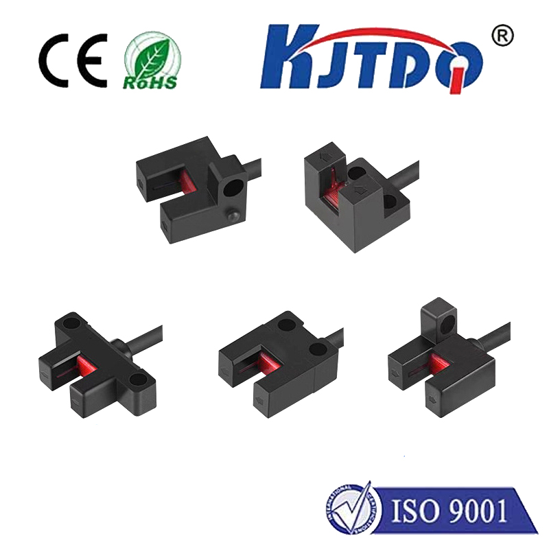
photoelectric relay
- time:2025-07-26 01:11:37
- Нажмите:0
Photoelectric Relays: The Optical Switching Revolution
Imagine switching heavy electrical loads silently, instantly, and without the wear and tear of physical contacts. This isn’t science fiction; it’s the everyday reality powered by photoelectric relays, a cornerstone of modern electronic control and isolation. These sophisticated components quietly enable safer, faster, and more reliable operations across countless industries, transforming how we manage power in sensitive or demanding environments.
Demystifying the Photoelectric Relay: Light as the Conductor
At its core, a photoelectric relay (also commonly known as an optically isolated relay, solid-state relay (SSR) with optical coupling, or simply an optoisolator used for switching) is an electronic switching device. Its brilliance lies in using light to control the flow of electricity between the input and output circuits, achieving complete electrical isolation.
Here’s how this elegant separation works:
- The Input Signal: A low-power electrical signal applied to the input terminals energizes an infrared light-emitting diode (IRED), typically made from materials like Gallium Arsenide (GaAs).
- Optical Coupling: This IRED emits infrared light. Crucially, this light travels across a tiny gap within the relay package. This gap is the heart of the isolation mechanism, physically separating the input and output sides.
- Light Detection: On the output side, a photosensitive device awaits. This is usually a phototransistor, a photodiode, a phototriac, or sometimes a more complex integrated circuit (like a photovoltaic MOSFET driver). This device detects the incoming infrared light.
- Output Switching: Upon detecting sufficient light, the photosensitive device activates. Depending on the device type and relay design:
- If it’s a phototransistor/diode driving an output transistor, it allows current to flow through the output terminals.
- If it’s a phototriac, it directly triggers the conduction state in AC applications.
- In MOSFET-based designs (common in DC SSRs), the light often powers a small photovoltaic cell that generates enough voltage to turn on the high-power output MOSFETs.
- Isolation Achieved: The only connection between input and output is light. This provides a critical isolation barrier, often rated for thousands of volts (isolation voltage), preventing dangerous voltages or electrical noise on the output side from affecting the sensitive low-voltage control circuitry on the input side.
Why Choose Light? The Compelling Advantages

Photoelectric relays offer significant advantages over traditional electromechanical relays (EMRs) in many applications:
- Exceptional Electrical Isolation: The primary advantage. The optical barrier provides inherent protection against voltage spikes, ground loops, and electromagnetic interference (EMI) traveling between circuits. This enhances system safety and reliability, especially where microcontrollers or PLCs control high-power loads.
- Silent, Spark-Free Operation: No moving parts means silent switching and no contact arcing. This eliminates a major source of electrical noise (EMI) and fire risk in explosive or volatile environments. They are intrinsically spark-free.
- Longer Service Life & Reliability: Without mechanical contacts that wear out from arcing, oxidation, or vibration, photoelectric relays boast an extremely long operational lifespan, often rated for hundreds of millions or even billions of cycles. Performance doesn’t degrade with use like EMR contacts.
- High-Speed Switching: The switching action via light is incredibly fast. Turn-on and turn-off times for photoelectric relays are typically measured in microseconds (µs) or milliseconds (ms), significantly faster than EMRs (tens of ms). This enables precise control in high-frequency applications.
- Vibration and Shock Resistance: The solid-state nature makes them highly resistant to physical shock and vibration, making them ideal for harsh industrial or mobile applications.
- Reduced EMI/RFI: The lack of contact arcing drastically reduces electromagnetic and radio-frequency interference generated by the switching action itself.
Addressing the Limitations: Informed Choices
While powerful, photoelectric relays aren’t a universal replacement for EMRs. Key considerations include:
- Heat Dissipation (Voltage Drop): Unlike EMRs which have almost zero voltage drop across closed contacts, semiconductor-based outputs have a small inherent voltage drop (e.g., 1-2V). This results in significant power dissipation (I²R losses) when switching high currents, requiring careful thermal management (heat sinks).
- Leakage Current (Off State): Even when “off,” solid-state outputs typically allow a small amount of leakage current (µA to mA) to flow. This needs consideration in safety-critical circuits or when switching very low-power devices.
- Inrush Current Handling: Some semiconductor outputs (like triacs) are sensitive to high inrush currents (e.g., from motor starts, tungsten lamps, power supplies). Special “snubber” circuits or relays rated for specific surge currents are often required.
- Complexity for AC Zero-Crossing: While many AC SSRs offer zero-crossing switching (turning on when AC voltage crosses zero) to minimize EMI and inrush current, implementing this adds complexity compared to simple EMR switching.
Where Light Powers Performance: Key Applications
The unique blend of isolation, speed, silence, and reliability makes photoelectric relays indispensable in numerous fields:
- Промышленная автоматизация: Controlling motors, solenoids, heaters, and sensors within PLC systems while isolating sensitive controllers from noisy power lines. Widely used in machine control and process automation.
- Medical Equipment: Providing critical isolation in patient monitoring, diagnostic instruments, and therapeutic devices where patient safety is paramount. Isolation prevents leakage currents from reaching the patient.
- Test & Measurement: Switching signals and power sources in sensitive test equipment without introducing ground loops or noise that could skew readings.
- HVAC Systems: Controlling compressors, fans, and heaters reliably in building management systems.
- Возобновляемые источники энергии: Managing switching in solar inverters and battery management systems (BMS).
- Consumer Electronics: Used internally in appliances for safe level shifting or controlling AC loads like heaters or pumps (less common than EMRs in simple appliances).
- Transportation: Reliable switching under harsh vibration conditions in automotive, aerospace, and railway systems.
- Telecom & Networking: Isolating data lines and providing safe switching in communication hubs.
Selecting the Right Photoelectric Relay
Choosing the optimal photoelectric relay involves matching specifications to the application:
- Load Type & Ratings: AC or DC? Required Напряжение and current levels? Consider both steady-state and peak/inrush currents.
- Input Control Type: Voltage required to trigger the input IRED? (e.g., 3-5V DC for TTL, 12-24V DC for industrial PLCs, AC control). Current requirements?
- Output Configuration: SPST (Single Pole Single Throw) or SPDT (Single Pole Double Throw)? Zero-crossing (AC) or random turn-on?
- Isolation Voltage: The critical safety rating specifying the maximum voltage the barrier can withstand between input and output.
- Switching Speed: Required turn-on/turn-off times?
- Mounting & Packaging: PCB mount, panel mount, DIN rail? With or without integrated heat sink?
- Special Features: Overvoltage protection, status indicators, logic-level compatibility?
The Future is Bright
Photoelectric relays represent a fundamental shift towards cleaner, faster, and more reliable electrical switching. Their ability to provide robust electrical isolation while handling significant power loads makes them a powerful tool in the engineer’s arsenal. As semiconductor technology advances, offering lower on-resistance MOSFETs, higher integration