измерение скорости вращения датчика приближения
- time:2025-07-19 08:50:36
- Нажмите:0
Proximity Sensor RPM Measurement: The Invisible Guardian of Rotational Speed
Imagine a world where critical machinery spins unseen, its vital signs unmonitored. From the turbines generating electricity to the engines propelling vehicles and the motors driving production lines, rotational speed (RPM) is a fundamental health indicator. Monitoring it isn’t just about performance; it’s about preventing catastrophic failure, optimizing efficiency, and ensuring safety. Enter the датчик приближения – an unassuming yet powerful device revolutionizing how we measure RPM non-invasively and reliably. This article delves into the synergy of proximity sensors and RPM measurement, exploring their principles, advantages, and vital applications.
Understanding the Core Components
First, let’s clarify the key players:
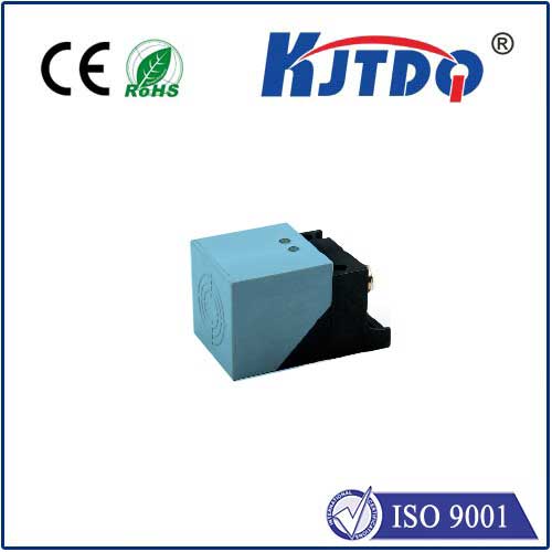
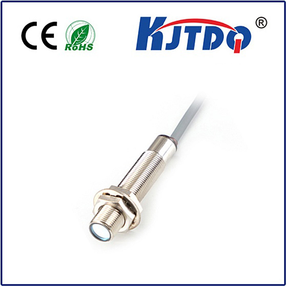
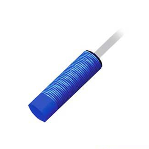
- Proximity Sensor: An electronic sensor that detects the presence or absence of a nearby object without physical contact. Common types used for RPM include:
- Inductive Proximity Sensors: Detect ferrous (iron-containing) metallic targets by generating an electromagnetic field. The target disrupts this field, triggering the sensor.
- Capacitive Proximity Sensors: Detect both metallic and non-metallic targets by sensing changes in capacitance caused by the target entering an electrostatic field.
- Hall Effect Sensors: Detect magnetic fields, typically triggered by a magnet attached to the rotating component. For RPM, inductive sensors targeting ferrous metal are most prevalent.
- RPM (Revolutions Per Minute): A fundamental unit measuring how many complete rotations a shaft, wheel, gear, or other component makes in one minute. It’s a critical parameter for monitoring performance, load, efficiency, and detecting issues like imbalance or bearing wear.
How Proximity Sensors Measure RPM: The Principle
The magic lies in transforming rotational motion into countable electrical pulses. Here’s the typical setup:
- Target Attachment: A target feature is attached to the rotating component whose speed needs measurement. This could be:
- A dedicated gear tooth or sprocket.
- A keyway or notch machined into the shaft.
- A simple bolt head or tab.
- (For Hall Effect) A small permanent magnet embedded or attached.
Sensor Positioning: The proximity sensor is mounted precisely near the path of the target feature, ensuring the target passes within the sensor’s detection range during each rotation. Crucially, there’s no physical contact between sensor and target.
Pulse Generation: As the component rotates:
- The target feature approaches the sensor.
- The sensor detects this presence (e.g., the metal tooth triggers the inductive field, a magnet triggers the Hall effect).
- The sensor’s internal electronics switch state, creating a distinct electrical pulse on its output line.
- The target moves away, the sensor reverts to its idle state.
- Pulse Counting & Calculation: A downstream device, such as a programmable logic controller (PLC), frequency counter, tachometer, or dedicated speed monitoring module, counts these pulses over a specific time interval.
- The fundamental formula:
RPM = (Number of Pulses per Rotation) * (Number of Pulses Counted) / (Counting Time in Minutes)
- Crucially, the system must know
n – the number of target features per rotation. A single target (n=1) means each pulse equals one revolution. A gear with 60 teeth (n=60) passing the sensor means 60 pulses per revolution. Knowing n allows accurate RPM calculation regardless of the number of targets.
Why Choose Proximity Sensors for RPM? Key Advantages
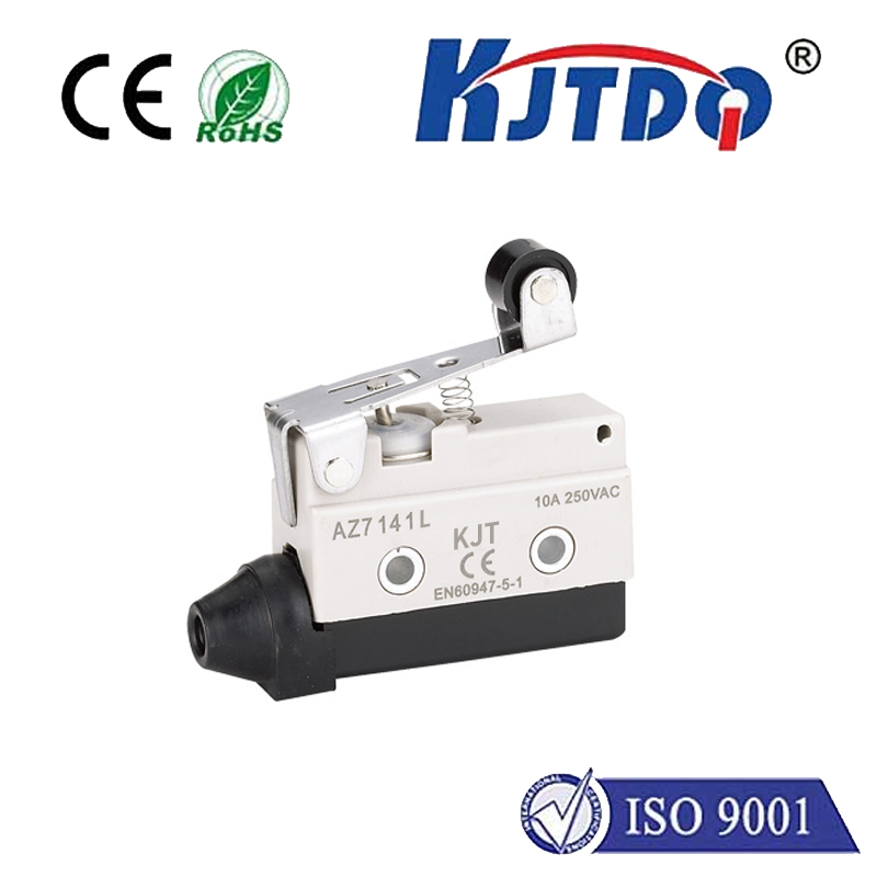
Compared to contact methods like mechanical tachometers or optical encoders (which can be sensitive to dirt/light), proximity sensors offer compelling benefits:
- Non-Contact Operation: Eliminates wear and tear on both the sensor and the rotating component. This translates directly to reduced maintenance costs and longer equipment lifespan.
- Robustness in Harsh Environments: Sealed inductive and Hall effect sensors excel in conditions where other sensors fail. They are largely immune to dust, dirt, oil, grease, moisture, and vibration – common foes in industrial and automotive settings.
- High Reliability and Accuracy: Solid-state electronics provide consistent, repeatable detection and pulse generation. When installed correctly and calibrated for the target, they deliver highly accurate RPM readings. The inherent immunity to environment enhances this reliability.
- Wide Speed Range Capability: Modern proximity sensors can detect targets passing at very high speeds, making them suitable for applications ranging from slow-moving heavy machinery to high-speed turbines and spindles.
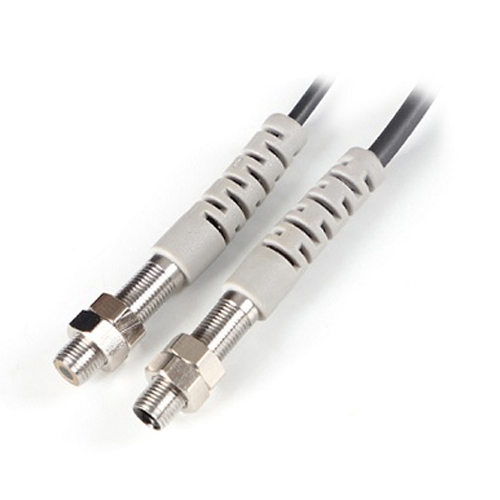
- Simple Installation and Integration: Mounting typically involves simple brackets, and the standard PNP/NPN outputs integrate easily with most industrial control and monitoring systems. Requires no slip rings or complex mechanical linkages.
Applications: Where Proximity RPM Measurement Shines
This technology is ubiquitous across industries:
- Промышленное оборудование: Monitoring motor, gearbox, pump, fan, conveyor, and spindle speeds in manufacturing plants. Critical for predictive maintenance.
- Automotive & Transportation: Measuring engine RPM (crankshaft/camshaft position sensors are often Hall effect or inductive), wheel speed (ABS systems), transmission input/output shaft speeds.
- Power Generation: Monitoring turbine shaft speeds in hydroelectric, steam, and gas turbine plants for control and overspeed protection.
- Аэрокосмическая деятельность: Monitoring engine RPM, auxiliary power units (APUs), and various accessory drives.
- Heavy Equipment: Tracking engine and drivetrain component speeds in construction and mining machinery.
- Rail & Marine: Measuring axle speeds, diesel engine RPM, and propeller shaft speeds.
Important Considerations
While powerful, optimal implementation requires attention:
- Target Material & Size: Inductive sensors require ferrous metal targets of sufficient size. Capacitive sensors need target material affecting capacitance. Ensure the target is appropriate for the sensor type.
- Sensor Sensing Distance: Mount within the specified range. Too far = unreliable detection. Too close risks physical damage from vibration or accidental contact.
- Target Features per Revolution (n): Accurate RPM calculation hinges on correctly defining
n. A system seeing 60 pulses per second with n=1 is 3600 RPM. With n=60, it’s only 60 RPM – a critical difference!
- Output Signal & Processing: Match the sensor output type (PNP/NPN, analog) to the input requirements of the counting device. Ensure the pulse processing unit can handle the maximum expected pulse frequency.
- Environment: While robust, extreme temperatures or strong electromagnetic interference near the sensor or cabling can affect performance. Always consult sensor specifications.
- Calibration: Initial setup often requires verifying the RPM reading against a known reference.
Выводы
Proximity sensor RPM measurement stands as a testament to elegant engineering solving a critical industrial challenge. By leveraging non-contact detection to generate precise electrical pulses from rotating components, it delivers unmatched robustness, reliability, and longevity in demanding environments. From ensuring the smooth hum of a factory floor to safeguarding the immense power of a turbine, this technology silently monitors the heartbeat of machinery. Understanding its principles, advantages, and implementation nuances empowers engineers and technicians to harness its potential, unlocking accurate speed data essential for optimization, protection, and peak operational performance.