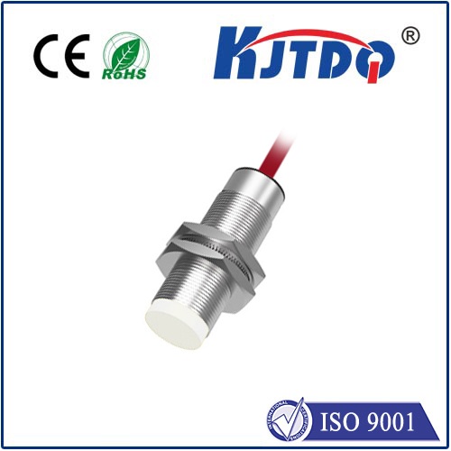
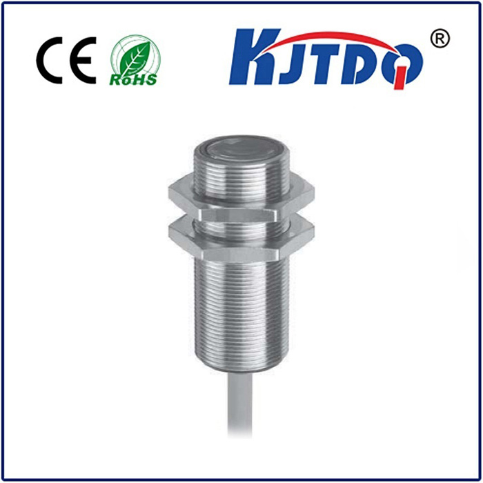
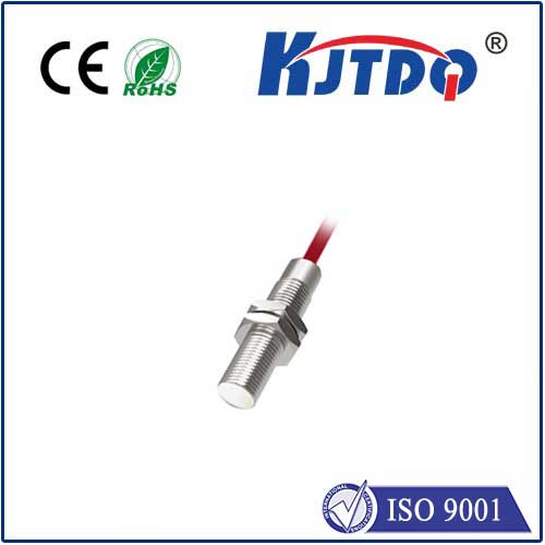
Ever installed a proximity sensor and found it frustratingly unresponsive, despite everything seeming wired correctly? Or perhaps you’ve been bewildered by terms like “PNP” and “NPN” on sensor datasheets? Understanding the fundamental difference between PNP and NPN proximity sensors – often simply referred to as “p and f sensors” in shorthand or part numbers – is critical for successful industrial automation, robotics, and machinery design. This seemingly minor distinction in electrical configuration dictates how the sensor interacts with your control system, impacting everything from wiring diagrams to PLC programming. Choosing incorrectly can lead to malfunctions, wasted time, and costly downtime. Let’s demystify these essential components and ensure you select the right “p” or “f” for the job.
The Core Distinction: Sourcing vs. Sinking Current
At their heart, both PNP and NPN proximity sensors perform the identical function: detecting the presence or absence of a target object without physical contact, typically using inductive (metal), capacitive, or photoelectric principles. The crucial difference lies not in how they sense, but in how they signal their state (detected/not detected) electrically to the control device, usually a Programmable Logic Controller (PLC) input module.
PNP Sensors (Often “P” in Part Numbers): Think of PNP as the “Positive Switching” sensor.
When a target is detected, the sensor switches on its internal electronic path, effectively connecting the positive supply voltage (+V, often +24V DC) to its signal output wire.
It sources current out of the signal output terminal to the PLC input.
Simplified View: PNP Output = “High” Signal (Supply Voltage) when Active/DETECTED. The output acts like a switch connecting the load (PLC input) to the positive supply rail.
Commonly associated with terms like “positive logic,” “sourcing output,” or sometimes indicated by a “P” in model numbers (e.g., PR18-8DP).
NPN Sensors (Often “N” or “F” in Part Numbers): Think of NPN as the “Negative Switching” sensor.
When a target is detected, the sensor switches on its internal electronic path, effectively connecting the signal output wire to the negative supply voltage (0V, GND).
It sinks current into the signal output terminal from the PLC input.
Simplified View: NPN Output = “Low” Signal (0V/GND) when Active/DETECTED. The output acts like a switch connecting the load (PLC input) to the negative supply rail (ground).
Commonly associated with terms like “negative logic,” “sinking output,” or sometimes indicated by an “N” or “F” in model numbers (e.g., LJ12A3-4-Z/FX).
Visualizing the Flow: Wiring Simplified
Imagine the electrical circuit:
Why Do Both Exist? Compatibility is Key
The existence of both types stems largely from historical conventions and regional preferences. Different PLC manufacturers initially favored different input circuit designs (sinking vs. sourcing input modules).
Crucially, modern PLCs frequently feature universal input modules that can accept either PNP or NPN signals by correctly wiring the common terminal. However, mismatching sensor output type and PLC input type remains one of the most common installation errors. Using a PNP sensor with a sourcing input PLC module (expecting to provide current) won’t work, nor will using an NPN sensor with a sinking input module (expecting to receive current).
Making the Right Choice: PNP vs. NPN
So, how do you choose?
Beyond the Acronyms: Real-World Applications
Whether PNP or NPN, proximity sensors are ubiquitous:
Key Takeaways for Flawless Integration
*
