proximity sensor fritzing
- time:2025-07-17 08:09:48
- Нажмите:0
Mastering Proximity Sensor Integration: Your Essential Fritzing Guide
Ever stared at a handful of wires, a proximity sensor, and an Arduino, mentally mapping connections only to second-guess yourself moments later? Welcome to the universal challenge of electronics prototyping! This is where Fritzing, the indispensable visual design tool, becomes your secret weapon for effortlessly turning proximity sensor concepts into tangible, testable circuits. Forget tangled messes and wiring errors – Fritzing provides the intuitive visual language to conquer proximity integration with confidence.
Understanding the Power Duo: Proximity Sensors and Fritzing
At its core, a датчик приближения detects the presence or absence of a nearby object without physical contact. Common types found in maker projects and IoT applications include:
- Infrared (IR) Proximity Sensors: Emit IR light and measure reflection.
- Ultrasonic Sensors: Send sound pulses and time their return (like the popular HC-SR04).
- Capacitive Sensors: Detect changes in capacitance caused by conductive objects.
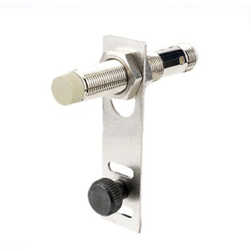
- Inductive Sensors: Detect metallic objects through electromagnetic fields.
Integrating these sensors often involves connecting their specific pins (VCC, GND, Signal/Output) to a microcontroller (like Arduino, ESP32, Raspberry Pi) and often additional components like resistors or capacitors.
This is precisely where Fritzing shines. It’s an open-source software specifically designed to bridge the gap between the physical components on your breadboard and the conceptual schematic diagram. Its drag-and-drop interface features realistic images of components (breadboard view) alongside schematic views and PCB layout views, making it the perfect tool for planning, documenting, and sharing proximity sensor projects.
Why Fritzing is Your Go-To Tool for Proximity Sensor Projects
- Visual Clarity & Error Prevention: Seeing a realistic representation of how the IR emitter/receiver, ultrasonic transducer, or capacitive pad connects to your Arduino pins drastically reduces wiring mistakes compared to relying solely on abstract schematics or text instructions. You immediately spot if you’ve crossed wires or plugged into the wrong header.
- Effortless Documentation: Creating professional-looking diagrams for project logs, tutorials, or sharing with collaborators is a breeze. Instead of sketching messy breadboards by hand, Fritzing generates clean, standardized images showing exactly how your proximity sensor is wired.
- Rapid Prototyping Iteration: Need to add a buzzer that activates when an object is detected? Or integrate an LED indicator? Fritzing allows you to quickly modify your virtual breadboard layout before touching a single physical wire, saving valuable time and component wear.
- Simplified Schematic Generation: While its schematic capabilities might not rival Eagle or KiCad for complex PCBs, Fritzing automatically generates a useful schematic view from your breadboard layout. This is invaluable for understanding the underlying electrical connections of your proximity circuit, especially for beginners.
- Abundant & Extensible Libraries: Fritzing comes loaded with standard components. Crucially, its vibrant community constantly creates and shares custom parts (Fritzing parts), meaning you can often find pre-made representations for popular proximity sensors like the HC-SR04, Sharp GP2Y0A21, or capacitive touch modules, streamlining your design process.
Crafting Your First Proximity Sensor Fritzing Diagram: A Step-by-Step Walkthrough
Let’s outline the typical process for creating a Fritzing diagram for a common proximity sensor setup (e.g., an ultrasonic sensor like the HC-SR04 with an Arduino Uno):
- Launch Fritzing & Select View: Open Fritzing and ensure you’re in the Breadboard view (the center icon at the top right).
- Add Core Components:
- Drag an Arduino Uno (or your specific board) from the “Parts” panel onto the breadboard canvas.
- Find your proximity sensor (e.g., search “HC-SR04” in parts). Drag it onto the canvas near the Arduino.
- Connect Power & Ground:
- Locate jumper wires in the parts panel. Drag one wire and connect one end to the Arduino’s
5V pin. Connect the other end to the sensor’s VCC (or +) pin.
- Drag another wire from the Arduino
GND pin to the sensor’s GND (or -) pin.
- Connect the Signal Pins:
- Identify the sensor’s output or trigger pins. For an HC-SR04:
Trig (Input) and Echo (Output).
- Drag a wire from the Arduino
D2 pin (you can choose any digital pin) to the HC-SR04’s Trig pin.
- Drag a wire from the Arduino
D3 pin to the HC-SR04’s Echo pin.
- (Note: Some sensors like common IR modules might only have a single analog or digital output pin).
- Add Supporting Components (If Needed):
- Sometimes resistors are needed (e.g., pull-up/down). Find a resistor in parts, place it, and connect its legs appropriately across the breadboard rows. Fritzing automatically handles color-coding based on resistor value. Adjust the value in the Inspector pane if needed.
- Refine and Document:
- Neaten wires by clicking and dragging bend points.
- Add labels to signal pins (right-click pin -> Add Label) like
Trig (D2) or Echo (D3) for clarity.
- Consider switching to the Schematic view to see the standard electrical representation Fritzing generated from your layout.
- Export & Share: Go to
File > Export > As Image... to save your diagram as a PNG or SVG for your project documentation, website, or forum post.
Beyond the Basics: Pro Tips for Proximity Sensor Fritzing
- Leverage the Community: Can’t find your specific sensor? Search online repositories like the official Fritzing parts repository or user forums. Many popular modules are readily available as downloadable
.fzpz files. Importing custom parts is straightforward and essential for niche components.
- Realism Matters: Position components realistically on the virtual breadboard. Mimic how they would physically sit, respecting pin spacing and orientations. This makes the diagram much more useful as a wiring reference.
- Label Everything: Don’t assume people (or future-you!) know which pin is which. Label sensor pins, Arduino digital/analog pins, and any critical connection points. Clarity is key.
- Utilize the Inspector: Select any component or wire to reveal the Inspector pane. Here you can change resistor values, capacitor values, component names, colors, and other properties to match your project specifics.
- Consider Schematic View: Once your breadboard view is solid, switch to the Schematic view. While Fritzing’s schematic generation can sometimes be messy, it provides a crucial check on the underlying circuit logic. Cleaning it up slightly can be worthwhile for complex projects or formal documentation. Understanding the schematic symbol for your sensor aids broader electronics literacy.
- Export Options: For wiring guides, the *Breadboard
