Датчик приближения Proteus
- time:2025-07-16 08:18:01
- Нажмите:0
Simulating Proximity Sensors in Proteus Design Suite: From Concept to Virtual Prototyping
The journey from a brilliant electronics concept to a functional prototype often involves costly components, potential hardware damage during testing, and significant time investment. What if you could rigorously test and refine your designs before soldering a single component? This is where the powerful combination of proximity sensors and Proteus Design Suite becomes invaluable. For engineers, students, and hobbyists alike, simulating proximity sensor circuits in Proteus offers a risk-free, efficient, and powerful pathway to successful design.
Understanding the Core Elements
First, let’s clarify the key players:
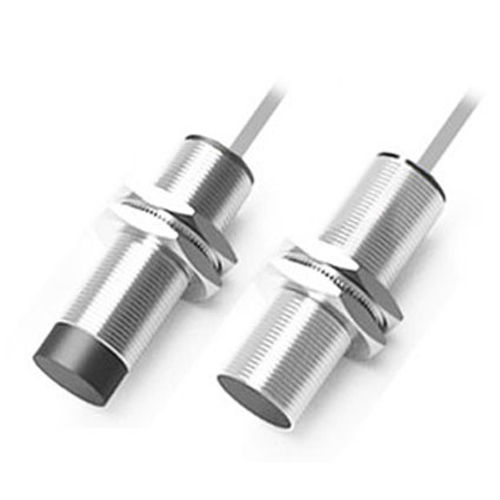
- Proximity Sensors: These are non-contact electronic devices that detect the presence or absence of nearby objects without physical touch. Common types include:
- Inductive: Detect metallic objects using electromagnetic fields. Ideal for industrial automation.
- Capacitive: Detect any material by sensing changes in capacitance. Used for liquid level sensing, touch interfaces, or non-metallic object detection.
- Infrared (IR): Use infrared light beams; detection occurs when an object interrupts (retro-reflective) or reflects (diffuse) the beam. Common in security systems and object avoidance.
- Ultrasonic: Measure distance using sound waves. Popular in robotics and parking sensors.
- Proteus Design Suite: A leading electronic design automation (EDA) software. Its core strengths lie in:
- Schematic Capture (ISIS): Creating detailed electronic circuit diagrams.
- PCB Layout (ARES): Designing printed circuit boards.
- Virtual System Modeling (VSM): This is the game-changer, allowing you to simulate the behavior of microcontrollers and associated electronic components (like our proximity sensors) running actual firmware, in real-time.
Why Simulate Proximity Sensors in Proteus?
The advantages of leveraging Proximity Sensor Proteus simulation are compelling:
- Cost Reduction: Eliminate the need for physical sensors and associated hardware during the initial design and testing phases. Iterate rapidly without purchasing components.
- Risk Mitigation: Safely test circuit behavior under various conditions (e.g., different object distances, materials, sensor failures) without risking damage to expensive microcontrollers or boards.
- Faster Development: Debug code and circuit interactions instantly. Identify and fix logical errors or timing issues long before building hardware.
- Enhanced Understanding: Visualize signal outputs, voltage levels, and timing diagrams within the simulation environment, deepening comprehension of sensor operation and circuit response.
- Accessibility: Experiment with a wide range of sensor types (inductive, capacitive, IR) that you might not physically have on hand.
How to Simulate Proximity Sensors in Proteus: A Practical Workflow
- Component Selection (Schematic Capture - ISIS):
- Open a new schematic in Proteus ISIS.
- Access the extensive component libraries (Component Mode).
- Search for relevant proximity sensor models. Proteus libraries include various IR sensors (like common reflective types OPB704/OPB705 equivalents), ultrasonic sensors (often modeled with transmitter and receiver elements), and generic proximity switches. Use keywords like
sensor, IR, proximity, ultrasonic.
- Place the chosen sensor model on the schematic sheet.
- Add supporting components: a microcontroller (e.g., PIC, Arduino models, ARM Cortex-M), resistors, LEDs for indication, power sources, and potentially signal conditioning circuits (like op-amps for capacitive sensors).
- Circuit Design & Wiring:
- Connect the sensor outputs to the microcontroller’s input pins (e.g., GPIO, ADC for analog sensors, or specific timer/capture pins for ultrasonic).
- Wire the microcontroller outputs to indicators (LEDs, LCD displays) or actuators.
- Ensure correct power supply connections (
VCC, GND).
- Firmware Development:
- Write or import the microcontroller firmware (e.g., C, assembly, Arduino sketch) using your preferred IDE (MPLAB X, Keil µVision, Arduino IDE, etc.).
- The code should initialize the microcontroller peripherals (GPIO, ADC, Timers, UART) and implement the logic to read the sensor’s state (digital HIGH/LOW or analog voltage) and control the outputs accordingly. For example:
if (IR_Sensor_Pin == LOW) { LED_On(); } // Object detected blocks IR beam- Read an ADC value for an analog distance measurement proxy.
- Simulation Execution (VSM):
- Associate the compiled microcontroller firmware (usually a
.hex or similar file) with the microcontroller component on your schematic (right-click -> Edit Properties).
- Initiate the Live Simulation by pressing Play.
- Observe Behavior: Watch the virtual circuit come to life. LEDs illuminate based on sensor detection. Use virtual instruments (Voltmeters, Oscilloscopes, Logic Analyzer) to probe signals.
- Interact: Proteus VSM allows interactive debugging. You can often manually trigger the sensor model (e.g., “activate” an IR sensor by bringing an object close in the schematic view) by clicking on it or using dedicated simulation controls. Observe how your firmware reacts instantly.
- Debugging and Refinement:
- If the circuit doesn’t behave as expected, pause the simulation.
- Use the Debug Menu to step through the microcontroller code line-by-line.
- Correlate the code execution with signal states shown on the schematic and instruments.
- Adjust component values (e.g., pull-up resistors), modify circuit connections, or refine the firmware logic based on observations. Rerun the simulation to verify fixes.
Advanced Capabilities: Simulating the Intangible
One of Proteus VSM’s strengths is simulating sensor behaviors that are difficult or expensive to replicate physically on a bench consistently:
- Analog Sensor Simulation: Model complex analog outputs representing distance (e.g., simulating the varying voltage from an IR distance sensor as an object moves closer/further). This is crucial for calibrating distance-dependent logic.
- Noise & Tolerance: Introduce signal noise or component tolerances into your simulation to see how robust your design is. (Note: Some advanced modeling might require specific SPICE models or careful configuration).
- Sensor Failure Modes: Test how your circuit handles sensor malfunctions like short circuits or open circuits.
Unlocking the Potential of Proteus Sensor Libraries
While Proteus provides a solid foundation with generic sensors and specific popular models, its power extends further:
- Custom Models: For highly specialized sensors, Proteus supports creating custom component models using SPICE or DLLs (though this requires advanced expertise).
- External Model Integration: Some sensor manufacturers provide simulation models (SPICE, IBIS, VHDL-AMS) that can be integrated into Proteus for higher-fidelity simulation.
A Cornerstone for Modern Electronics Design
For projects involving automation, robotics, security, IoT, or any system interacting with its environment, proximity sensors are fundamental. Proteus Design Suite empowers you to take control of this critical aspect. By mastering Proximity Sensor Proteus simulation, you transition from guesswork to precision engineering. It streamlines the design process, fosters deeper understanding, accelerates debugging, and ultimately leads to more reliable and successful hardware implementations. Whether you’re a student learning sensor interfacing or a seasoned engineer optimizing a complex system, integrating proximity sensor simulation with Proteus VSM