proximity sensor interfacing with arduino
- time:2025-07-15 08:49:13
- Нажмите:0
Proximity Sensor Interfacing with Arduino: Bring Detection to Your Projects
Ever wanted your Arduino projects to see the world around them without physical contact? To know when an object approaches, a door closes, or a machine part is in position? That’s precisely the power unlocked by proximity sensor interfacing with Arduino. These remarkable devices allow microcontrollers to perceive the presence, absence, or distance of nearby objects silently and efficiently. Whether you’re building a touchless switch, an automatic faucet, a robot avoiding obstacles, or a sophisticated industrial monitor, mastering proximity sensor integration is an essential skill. This guide dives deep into the practical steps, considerations, and code examples to seamlessly connect various proximity sensors to your Arduino board.
Understanding the Proximity Sensor Family
Before connecting wires, it’s vital to grasp that “proximity sensor” is an umbrella term. Different technologies serve distinct purposes:
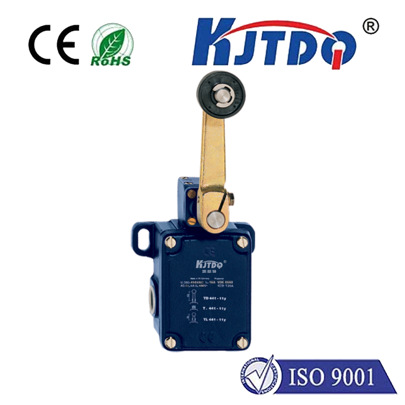
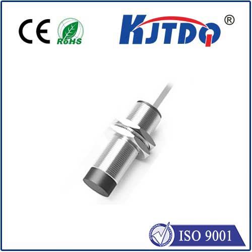
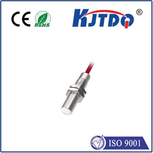
- Inductive Proximity Sensors: Detect metallic objects using an electromagnetic field. Ideal for industrial settings (e.g., counting metal parts, sensing machine arm positions). They ignore non-metals like plastic, wood, or liquid.
- Capacitive Proximity Sensors: Detect any material (metal, plastic, wood, liquid, even your hand) by sensing changes in capacitance. Perfect for level detection in tanks (liquids, granules) or touchless interfaces.
- Infrared (IR) Proximity Sensors: Emit IR light and detect its reflection. Common low-cost modules (like the popular HC-SR04, though technically a distance sensor) fall here. Great for object detection at short to medium ranges, obstacle avoidance robots, and presence detection. Be aware of ambient IR light interference.
- Ultrasonic Sensors: Emit sound waves beyond human hearing and measure the echo time to calculate distance. Highly effective for distance measurement and object detection over longer ranges compared to basic IR, and less affected by light or color. The HC-SR04 is the quintessential Arduino ultrasonic sensor.
- Magnetic Proximity Sensors (Reed Switches/Hall Effect): Detect the presence of a magnetic field. Used in door/window security sensors or sensing rotational speed (using magnets). Hall effect sensors provide digital or analog output depending on the type.
Choosing the right sensor hinges critically on your application: What material needs detection? What detection range is required? What environmental factors (dust, light, moisture) are present? What output signal (digital ON/OFF or analog varying voltage) suits your needs best?
Interfacing Basics: Wiring it Up
Most common proximity sensors interfacing with Arduino follow similar wiring principles. Here’s a breakdown, focusing on digital output sensors (which provide a simple HIGH/LOW signal) and analog output types:
- Digital Output Sensors (e.g., Inductive, Capacitive Switches, Digital Hall):
- VCC (Voltage): Connect to the Arduino’s 5V pin (or 3.3V if specifically a 3.3V sensor - always check the datasheet!).
- GND (Ground): Connect to any Arduino GND pin.
- OUT (Signal): Connect to a digital input pin on the Arduino (e.g., D2, D3, D4…). These sensors act like a switch: Output goes HIGH (or LOW) when an object is detected within range. A pull-up or pull-down resistor might be needed internally (often built-in) or externally depending on the sensor module and logic type (NPN/PNP sourcing/sinking).
- Analog Output Sensors (e.g., Some IR, Some Hall Effect):
- VCC: Connect to Arduino 5V (or 3.3V as specified).
- GND: Connect to Arduino GND.
- OUT: Connect to an analog input pin on the Arduino (A0, A1, A2…). These sensors provide a varying voltage proportional to distance or field strength, offering more granularity than a simple ON/OFF.
Crucially: Always consult the sensor’s datasheet. It details the exact wiring, voltage requirements (using 5V on a 3.3V sensor can destroy it!), output signal type, and logic levels.
Bringing it to Life: Arduino Programming
The Arduino code reads the sensor’s signal. The approach differs slightly between digital and analog sensors.
- Reading Digital Sensors (Simple ON/OFF Detection):
const int sensorPin = 2; // Digital pin connected to sensor OUT
void setup() {
Serial.begin(9600); // Start serial communication
pinMode(sensorPin, INPUT); // Set pin as input
}
void loop() {
int sensorState = digitalRead(sensorPin); // Read the state
if (sensorState == HIGH) { // Or LOW, depends on sensor logic!
Serial.println("Object Detected!");
// Take action: turn on LED, activate relay, etc.
} else {
Serial.println("No Object");
// Turn off related outputs
}
delay(100); // Small delay for readability
}
Key Points:
- Determine if the sensor output is active-HIGH (goes HIGH when detected) or active-LOW (goes LOW when detected). Your
if condition depends on this!
- Adjust the
delay() based on how quickly you need to detect changes.
- Reading Analog Sensors (Measuring Distance or Field Strength):
const int sensorPin = A0; // Analog pin connected to sensor OUT
void setup() {
Serial.begin(9600);
// Analog pins are set as INPUT by default
}
void loop() {
int sensorValue = analogRead(sensorPin); // Read analog value (0-1023)
Serial.print("Raw Value: ");
Serial.println(sensorValue);
// Often requires conversion to meaningful units (e.g., cm, inches, gauss)
// float distance_cm = map(sensorValue, minRaw, maxRaw, minDistance, maxDistance); // Basic linear scaling
// float distance_cm = someCalibrationFormula(sensorValue); // More complex mapping
// Use distance_cm for thresholds or actions
delay(50);
}
Key Points:
analogRead() returns a value between 0 (0V) and 1023 (~5V).- Calibration is crucial! You need to map this raw value to a real-world unit (like centimeters or millitesla). This involves testing the sensor at known distances or field strengths and finding the relationship (often linear, but not always). Use
map() for simple linear conversions or create a custom function. Refer to the sensor datasheet for conversion formulas if available.
Key Considerations for Reliable Operation
Successfully interfacing proximity sensors with Arduino goes beyond just wiring and basic code. Keep these factors in mind:
- Power Supply: Ensure your power source (USB or external) can handle the sensor’s current draw, especially if using multiple sensors or sensors with integrated LEDs/relays. Insufficient power causes erratic behavior.
- Sensor Range: Every sensor has a specified nominal sensing range. Objects outside this range won’t be reliably detected. Check the datasheet.
- Environmental Factors:
- IR Sensors: Highly susceptible to strong ambient light (sunlight, incandescent bulbs). Shield the sensor if possible. Consider ultrasonic alternatives in bright environments.
- *Ultrasonic