proximity sensor for rpm measurement
- time:2025-07-15 08:43:16
- Нажмите:0
Proximity Sensors: The Ultimate Guide to Non-Contact RPM Measurement
In the intricate world of rotating machinery – from massive industrial motors to delicate precision instruments – accurately monitoring rotational speed (RPM) is paramount. It’s the vital sign indicating performance, efficiency, and the onset of potential failure. While traditional methods like mechanical tachometers or encoders exist, they often introduce friction, wear, or simply won’t withstand harsh environments. This is where the unassuming yet incredibly robust датчик приближения steps into the spotlight, offering a superior solution for reliable, non-contact RPM measurement.
Understanding the Proximity Sensor Advantage
At its core, a proximity sensor is a device that detects the presence or absence of an object without physical contact. When applied to RPM measurement, its forte lies in non-contact detection. This fundamental characteristic eliminates several critical drawbacks:
- Zero Mechanical Wear: By never touching the rotating part, the sensor and the target suffer no friction-induced degradation, extending their operational lifespan drastically.
- Harsh Environment Immunity: Sealed designs make proximity sensors ideal for environments plagued by oil, grease, coolant, dust, vibration, or high temperatures – conditions where optical sensors or mechanical contacts would swiftly fail.
- High-Speed Capability: Unburdened by inertia or contact limits, certain proximity sensors can detect rapid movements and targets spinning at tens or even hundreds of thousands of RPM.
- Simplicity and Reliability: With no moving parts to wear out or break, proximity sensors offer exceptional long-term stability and reduced maintenance needs.
Decoding the How: Turning Detection into RPM Value
So, how does sensing presence translate into a rotational speed value? The magic lies in counting events over time. Here’s the typical process:
- Target Preparation: A metallic target (like a gear tooth, keyway, bolt head, or a dedicated pin/flag) is attached to the rotating shaft or component whose RPM needs measuring. For smoother surfaces, a specially designed gear tooth or notched wheel target is often used.
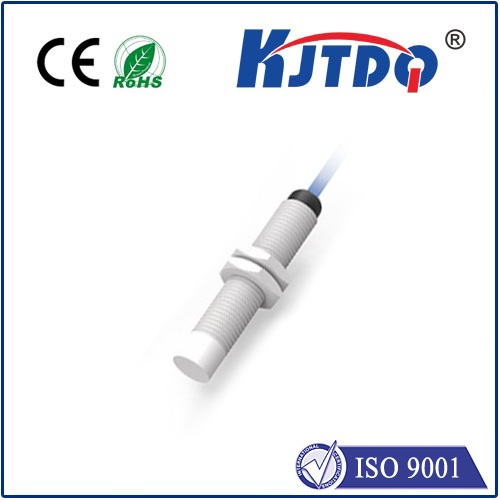
- Sensor Positioning: An индукционный датчик приближения (the most common type for this application due to its cost-effectiveness and reliability with metals) is mounted close to the path of the rotating target – typically just a few millimeters away. Its sensing face points towards the passing targets.
- Detection Event: As each target passes in front of the sensor’s active face, it disrupts the sensor’s electromagnetic field. This disruption is detected by the sensor.
- Pulse Generation: The sensor internally converts each successful detection into a clean, digital output pulse (often a switch to ground or supply voltage, depending on PNP/NPN configuration).
- Counting and Timing: These output pulses are fed into a frequency counter, tachometer module, Programmable Logic Controller (PLC), or data acquisition system. This device counts the number of pulses received within a precisely defined time period (e.g., one second).
- RPM Calculation: Knowing the number of pulses per revolution (PPR) – which is equal to the number of targets passing the sensor per full rotation – the system calculates RPM. The fundamental formula is:
RPM = (Pulses Counted per Time Period) * (60 seconds/minute) / (Pulses per Revolution) / (Time Period in seconds)
- Example: If a shaft has 1 target (PPR = 1), and you count 10 pulses in 1 second: RPM = (10) * 60 / 1 / 1 = 600 RPM.
Putting Proximity Sensors to Work: Key Applications
The versatility of non-contact RPM measurement using proximity sensors makes them indispensable across numerous sectors:
- Motor & Pump Monitoring: Continuously track motor speed for process control, overload detection, or verifying variable frequency drive (VFD) performance. Monitor pump RPM to ensure flow rates and detect cavitation or dry running.
- Gearbox & Drivetrain Analysis: Measure input/output shaft speeds to calculate gear ratios, detect slippage in clutches or belts, and identify bearing issues manifesting as speed variations.
- Conveyor Systems: Ensure proper belt speed synchronization across multiple drives, detect belt slippage, and trigger actions based on counted packages/items.
- Turbine & Compressor Overspeed Protection: Provide critical, real-time speed feedback to safety systems designed to shut down equipment before catastrophic overspeed events occur.
- Engine Test Benches: Precisely measure crankshaft RPM as a fundamental parameter in performance testing and diagnostics.
Optimizing Your RPM Measurement Setup: Practical Considerations
To harness the full potential of proximity sensors for accurate RPM measurement, attention to detail during setup is crucial:
- Sensor Type Selection: Inductive proximity sensors are the default choice for ferrous (iron/steel) targets due to their robustness and cost. For non-ferrous metals (aluminum, brass, copper), ensure the sensor is specifically rated for them, as detection distances may be reduced. Capacitive sensors (for non-metals) or specialized optical sensors are alternatives for unique material cases.
- Target Design and PPR: The number of targets determines the Решимость and Частота of the signal. One target (PPR=1) is simplest but provides only one pulse per revolution, limiting resolution at lower speeds. Multiple targets (e.g., a gear tooth wheel) provide more pulses per revolution, increasing resolution and allowing faster speed detection. Target size and material must be compatible with the sensor’s specifications.
- Air Gap Precision: Maintain the recommended gap between the sensor face and the target path specified by the manufacturer. Too large a gap reduces signal strength; too small risks physical collision. Use mounting brackets for stability.
- Sensor Orientation: Ensure the sensor is mounted perpendicular to the target path for maximum signal strength and reliability, especially with small targets.
- Electrical Integration: Choose the correct sensor output type (PNP vs. NPN, N.O. vs. N.C.) to match your control system (PLC, counter, etc.). Ensure proper wiring (shielding for long cable runs in noisy environments) and power supply compatibility. Protect the output from voltage spikes, especially when driving relays or inductive loads. Proper shielding is often critical.
- Signal Processing: Raw sensor pulses are digital, but may need conditioning (debouncing, amplification) depending on the counter/tachometer input requirements. Modern digital counters and PLCs often handle this internally. Sampling time selection on the counter/tachometer balances responsiveness and stability.
Beyond the Basics: Advantages Over Alternatives
While technologies like optical encoders or Hall effect sensors also enable non-contact RPM measurement, inductive proximity sensors often hold distinct advantages:
- Долговечность: Superior resistance to contamination (dirt, oil, dust) compared to optical sensors.
- Cost-Effectiveness: Generally more affordable than high-resolution encoders and simpler to install than Hall effect sensors requiring magnets.
- Robustness: Less susceptible to alignment issues than optical interrupts and immune to magnetic field interference affecting Hall sensors in certain environments.
- Simplicity: A straightforward “pass/fail” detection mechanism translates into reliable signals for counting. Time-based measurement replaces complex analog signal processing.
For countless industrial applications demanding reliable, maintenance-free RPM measurement in challenging conditions, the proximity sensor is frequently the optimal solution. Its inherent toughness, non-contact operation, and straightforward integration make it a cornerstone technology for monitoring the vital pulse of rotating equipment. By understanding the principles of detection, pulse generation, and counting, engineers can effectively
