inductive proximity sensor raspberry pi
- time:2025-07-11 02:48:51
- Нажмите:0
Bridging Worlds: Connect Inductive Proximity Sensors to Your Raspberry Pi Project
Title: Unlock Industrial Sensing: Using Inductive Proximity Sensors with Raspberry Pi
Imagine adding industrial-grade reliability to your Raspberry Pi project. Detecting metal objects with precision, immune to dust, moisture, or oil – that’s the power inductive proximity sensors bring to the table. While Raspberry Pi excels at computation and control, its native GPIO pins aren’t designed for the rugged world of factory automation sensors. Connecting an inductive proximity sensor to Raspberry Pi requires understanding the fundamental voltage mismatch and the elegant solutions to bridge it. This guide dives into the why and how, empowering you to integrate robust non-contact metal detection into your Pi-powered creations.
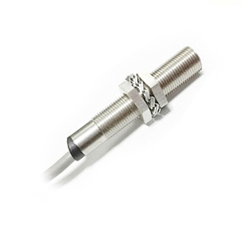
Understanding the Inductive Proximity Sensor
Inductive proximity sensors are stalwarts of industrial automation. They work on the principle of electromagnetic induction. Inside the sensor’s head is a coil generating a high-frequency oscillating electromagnetic field. When a metallic target (like steel, aluminum, brass, copper, etc.) enters this field, it induces small eddy currents within the target. These currents absorb energy from the sensor’s coil, causing a measurable change in the oscillation – usually a drop in amplitude. The sensor’s internal electronics detect this change and trigger its output switch.
Key characteristics making them ideal for many applications:

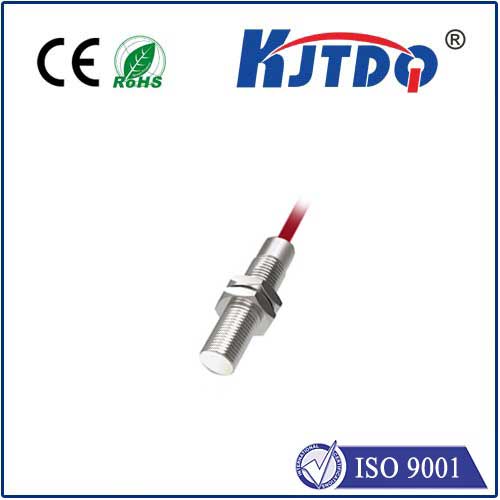
- Non-contact Operation: No physical touch required, minimizing wear and tear.
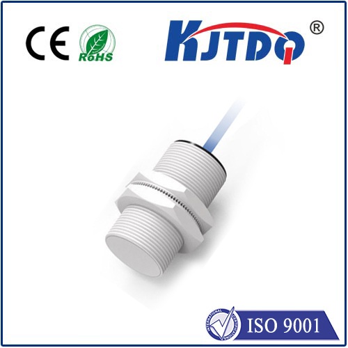
- Ruggedness: Typically housed in robust metal or polymer casings, resistant to harsh environments (dust, liquids, vibrations).
- Speed: Capable of detecting objects at very high speeds.
- Long Life: Absence of mechanical contacts translates to exceptional lifespan.
- Output Types: Primarily available as NPN (Sinking) or PNP (Sourcing) transistor outputs, providing a clean on/off signal (often referred to as a digital sensor). Common configurations are 3-wire (Power +, Power -, Signal) or sometimes 2-wire.
The Raspberry Pi GPIO Challenge
Here’s the core issue pushing us beyond simple direct connection:
- Sensor Operating Voltage: Industrial inductive proximity sensors typically require a DC supply voltage between 10-30V, commonly 12V or 24V.
- Sensor Output Voltage: When active (target detected), an NPN sensor pulls its output signal line down to 0V relative to its own negative supply. A PNP sensor pulls its output signal line up to its positive supply voltage (e.g., 12V or 24V).
- Raspberry Pi GPIO Limitation: The Raspberry Pi’s General Purpose Input/Output (GPIO) pins operate at 3.3V logic levels. Applying a voltage higher than 3.3V (or pulling a pin below 0V) risks permanent damage to the Raspberry Pi.
Directly connecting the sensor’s output signal wire to a Pi GPIO pin is a recipe for a dead Pi if the sensor uses a higher supply voltage! We need an interface – a safe bridge – between these two voltage worlds.
Interface Solutions: Safely Connecting Sensor to Pi
Two primary, reliable, and cost-effective methods exist:
- Using an Optocoupler (Opto-isolator): This is often the preferred and safest method.
- How it Works: An optocoupler contains an LED (Light Emitting Diode) on the input side and a photosensitive transistor on the output side. They are electrically isolated from each other, only coupled by light.
- Wiring (Example for an NPN Sensor):
- Sensor (+) to +12V/24V Supply.
- Sensor (-) to Supply GND (and Raspberry Pi GND).
- Sensor Signal to one side of the optocoupler’s input LED.
- The other side of the optocoupler’s LED connects via a suitable current-limiting resistor (e.g., ~1kOhm for 12V) to the +Supply.
- The optocoupler’s output transistor Collector connects to a Raspberry Pi 3.3V pin.
- The output transistor Emitter connects to a Raspberry Pi GPIO pin configured as INPUT.
- Add a pull-down resistor (e.g., 10kOhm) from the GPIO pin to Pi GND. (Important!)
- Operation: When the NPN sensor detects metal, it activates, sinking current. This completes the circuit, lighting the optocoupler’s LED. The light activates the photosensitive transistor, pulling the GPIO pin (via the connection to 3.3V) HIGH. Without a target, the LED is off, the transistor is off, and the pull-down resistor pulls the GPIO pin LOW. For a PNP sensor, the wiring to the optocoupler LED is reversed.
- Преимущества: Galvanic isolation (protects the Pi from voltage spikes/noise), simple design, readily available components.
- Using a Relay Module:
- How it Works: A small signal relay module uses the sensor’s output to control an electromechanical relay. The relay’s contacts open or close a separate circuit compatible with the Pi.
- Wiring:
- Connect the sensor to its power supply as per its specification.
- Connect the sensor’s signal output to the relay module’s control input terminals (ensuring voltage compatibility).
- Connect one contact of the relay to a Raspberry Pi GPIO pin configured as INPUT.
- Connect the other relay contact to Raspberry Pi GND.
- Enable the internal pull-up resistor on the Raspberry Pi GPIO pin or add an external pull-up resistor from the pin to 3.3V.
- Operation: When the sensor activates, it energizes the relay coil. The relay contacts close, connecting the Pi GPIO pin to GND. The Pi reads this as a LOW (0V) signal. When the sensor is inactive, the relay opens, and the pull-up resistor pulls the GPIO pin HIGH (3.3V).
- Преимущества: Handles potentially higher currents (if needed elsewhere), very audible/visible click. Disadvantages: Mechanical wear, slower switching speed, potential for contact bounce.
Choosing Between Optocoupler and Relay
| Особенности |
Optocoupler |
Relay Module |
| Isolation |
High (Galvanic) |
Good (Coil/Contact Separation) |
| Speed |
Very Fast (ns/µs) |
Slow (ms range) |
| Wear |
None (Solid State) |
Mechanical contacts wear out |
| Noise |
Silent |
Audible Click |
| Current |
Low (mA) |
Can handle higher currents |
| Complexity |
Simple electronic circuit |
Simple module connection |
For most proximity sensing tasks involving Raspberry Pi, optocouplers offer the best combination of speed, reliability, noise immunity, isolation, and lifespan.
Reading the Sensor in Python
Once wired correctly (using either method), reading the sensor state is straightforward in Python using a library like RPi.GPIO or gpiozero.
Example using gpiozero (Assume sensor “active” pulls GPIO pin LOW via relay method):
”`python
from gpiozero import Button # Button is good for a simple on/off input
from signal import pause
Initialize a Button on GPIO 17, pull_up