pnp no proximity sensor
- time:2025-07-09 03:03:14
- Нажмите:0
PNP Proximity Sensor Missing? Diagnosing the “No Sensor” Dilemma in Automation
Imagine a critical assembly line grinding to a halt. Machines stop communicating, safety protocols fail, and the frantic search begins. One culprit often overlooked? The absence or failure of a seemingly simple component: a PNP proximity sensor. When your system signals a PNP no proximity sensor error, it’s not just a minor glitch—it’s a red flag demanding immediate attention to restore productivity and safety. Understanding why this happens and how to resolve it is fundamental for anyone working with industrial automation.
Understanding the PNP Proximity Sensor: The Unsung Hero
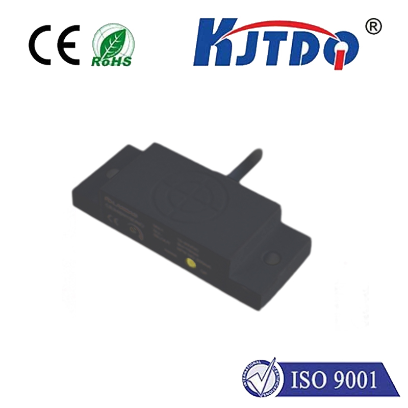
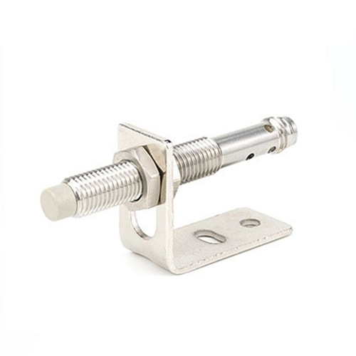
Before diving into the problem, let’s clarify the star of the show. A PNP proximity sensor is a ubiquitous non-contact switching device. It detects the presence or absence of metallic objects (sometimes other materials, depending on type) without physical contact. “PNP” refers to its electrical output configuration: it sources current to the load when active. Think of it as a switch that provides a positive voltage signal (“ON” state) when an object is detected within its sensing range.
These sensors are vital for countless tasks:

- Position Verification: Confirming parts are in place before a process begins.
- Object Counting: Tracking items on a conveyor.
- End-of-Travel Detection: Signaling when a cylinder is fully extended or retracted.
- Safety Interlocks: Ensuring guards are closed before machinery starts.
- Level Detection: Monitoring fill levels in bins or tanks.
In essence, they are the “eyes” feeding crucial positional data to controllers (PLCs), driving logic, and enabling automated sequences. When one is missing or malfunctioning, the consequences ripple through the entire system.
Decoding “No Proximity Sensor” – More Than Meets the Eye
The message “PNP no proximity sensor” (or similar variations) appearing on an HMI (Human-Machine Interface) or PLC diagnostic screen can stem from several root causes, not always implying the sensor is physically absent:
- Physical Absence or Disconnection: The simplest explanation. The sensor might not have been installed, has been accidentally removed, or its wiring harness is completely disconnected or severed. Always visually and physically inspect the sensor location first. Check the mounting bracket and cable integrity back to the junction box or controller.
- Power Supply Failure: Even if physically present, a sensor needs power to operate. A blown fuse, tripped circuit breaker, faulty power supply unit, or a broken wire within the +V supply line (typically brown wire) will render the sensor invisible to the system, mimicking a “no sensor” state. Verify power availability directly at the sensor’s terminals using a multimeter.
- Wiring Faults (Open Circuit): Beyond complete disconnection, wiring issues are a prime suspect. This includes:
- Broken Wire: A severed conductor inside the cable, often near strain relief points or connectors.
- Loose Connection: Terminals not tightened properly at the sensor, junction box, or controller input card can cause intermittent or complete loss of signal.
- Incorrect Wiring: Misidentifying the PNP output wire (typically blue for common/0V, black for signal output) and connecting it wrongly to the PLC input module. PNP sensors require sinking inputs on the PLC. Connecting a PNP sensor to a sourcing input (designed for NPN) will not work.
- Sensor Failure: Internal electronic components can fail due to voltage spikes, extreme temperatures, physical damage (impact, crushing), moisture ingress (especially in non-rated sensors), or simply end-of-life.
- PLC Input Module Failure: While less common, the specific channel on the PLC’s input card designated for that sensor could be faulty. Testing the sensor independently or swapping it with a known-good input channel helps diagnose this.
- Configuration/Programming Error: The PLC program expects a signal from a specific physical input point corresponding to that sensor. If the wiring was changed without updating the PLC program, or the input address is incorrectly mapped in the logic, the system will report the sensor as missing even if it’s physically present and working. Double-check the I/O mapping in the PLC configuration software.
The High Cost of a Missing Signal
Ignoring a PNP no proximity sensor alert isn’t an option. The repercussions are significant:
- Production Downtime: Machines halt, cycles stop, throughput plummets. Every minute counts in manufacturing.
- Quality Issues: Without sensor verification, defective products might pass through, or processes occur out of sequence, leading to scrap and rework.
- Safety Hazards: Critical safety interlocks relying on proximity sensors become compromised, potentially putting operators and equipment at risk. This is the most severe consequence.
- Diagnostic Time & Cost: Troubleshooting takes time and skilled personnel, adding unexpected labor costs.
- Component Stress: Other system parts might be stressed if machine sequences attempt to run without proper positional feedback.
Systematic Troubleshooting: Finding the Missing Link
Effectively resolving a PNP no proximity sensor issue requires a methodical approach:
- Visual Inspection: Start here! Is the sensor physically present and securely mounted? Is its cable intact and connected?
- Check Power: Using a multimeter, measure the voltage between the sensor’s +V (brown) and 0V (blue) terminals. Ensure it matches the sensor’s rating (e.g., 10-30V DC). No power? Trace back to the source (fuses, power supply).
- Verify Output Signal:
- Power the sensor if necessary.
- With a multimeter (DC Voltage mode), measure between the sensor’s Signal wire (usually black) and 0V (blue).
- Activate the sensor (bring a metal target close).
- A functional PNP sensor will show near the supply voltage (e.g., 24V) when activated and near 0V when not activated. If you get no voltage change, the sensor output is likely dead.
- Check Wiring Continuity: Use a multimeter in continuity/diode mode to check for breaks between the sensor connector and the PLC terminal block. Check all wires: +V (brown), Output (black), and 0V (blue).
- Validate PLC Input:
- Check the PLC diagnostic LEDs for the specific input point. Does it light up when the sensor should be active?
- If possible, use the PLC programming software to monitor the input status in real-time. Does it react to sensor activation?
- Temporarily swap the sensor’s signal wire to a known-good PLC input channel. If it works, the original PLC input channel might be faulty.
- Sensor Swap Test: If you have a spare, identical PNP proximity sensor, replace the suspect one. If the problem disappears, the original sensor is faulty.
- Review PLC Program: Consult the control logic documentation. Ensure the physical sensor wiring matches the input address used in the PLC program. Verify the logic expects and uses this input correctly.
Prevention: Avoiding the “No Sensor” Scenario
Proactive measures significantly reduce the chances of encountering this error:
- Robust Installation: Secure sensors properly using appropriate brackets. Ensure cables are routed safely away from moving parts, sharp edges, heat sources, and potential crushing points. Use conduit or cable carriers where necessary. Proper strain relief at connections is critical.
- Correct Wiring Practices: Follow manufacturer wiring diagrams meticulously. Use high-quality cables and connectors. Label all wires clearly at both ends. Double-check PNP vs. NPN configurations match between sensors and PLC inputs.
- Stable Power Supply: Ensure clean, stable DC power within the sensor’s specified range. Consider adding surge protection devices on power lines near the sensors.
- Regular Maintenance: Include sensors in your PM schedule. Periodically clean sensing faces, verify mounting integrity, check connections for tightness and corrosion, and perform functional checks.
- Documentation: Maintain accurate and up