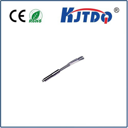
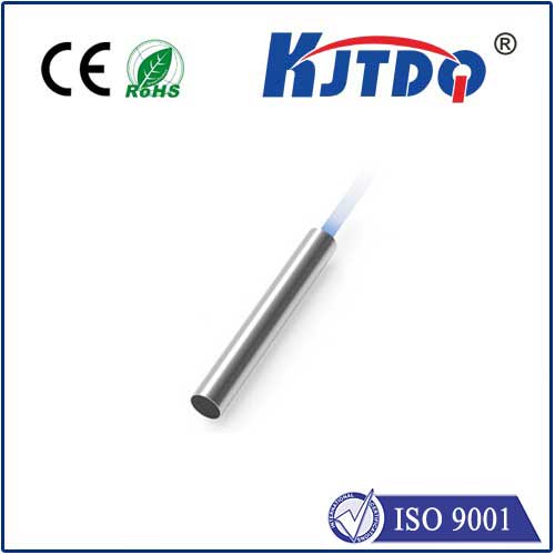
inductive position transducer proximity sensor
- time:2025-06-28 01:06:29
- Нажмите:0
Demystifying the Workhorse: Your Guide to Inductive Position Transducer Proximity Sensors
Inductive Position Transducer Proximity Sensor: The Core of Non-Contact Precision Sensing
In the intricate dance of modern automation, robotics, and industrial control, knowing the precise location or detecting the presence of a metallic object—without ever touching it—is fundamental. Enter the unsung hero: the inductive position transducer proximity sensor. This robust and highly reliable device elegantly combines the principles of electromagnetic induction to perform two critical, often intertwined, tasks: measuring linear or angular position and detecting proximity of metallic targets. If your operations involve metals and demand durability, precision, and non-contact operation, understanding this technology isn’t just useful—it’s essential. Let’s delve into how it works and why it’s ubiquitous in demanding environments.
The Core Principle: Harnessing Eddy Currents
At its heart, an inductive sensor relies on a simple yet powerful physical phenomenon: electromagnetic induction. Here’s the breakdown:
- Generating the Field: The sensor contains a coil of wire wound around a ferromagnetic core. When an alternating electrical current (AC) passes through this coil, it generates an oscillating electromagnetic field radiating outwards from the active face of the sensor.
- Target Interaction: When a conductive metal target (like iron, steel, aluminum, brass, or copper) enters this electromagnetic field, eddy currents are induced within the target material itself. These are small swirling currents that flow in opposition to the sensor’s own field.
- Field Disturbance: The creation of these eddy currents consumes energy. This energy loss manifests as a measurable disturbance or damping of the sensor’s original oscillating electromagnetic field.
- Detection and Measurement: The sensor’s internal electronics continuously monitor the characteristics of its own field (often the amplitude of the oscillation). The damping effect caused by the eddy currents alters these characteristics. By precisely measuring this change – be it the reduction in oscillation amplitude or a shift in resonant frequency (depending on the sensor design) – the sensor can determine two key things:
- Proximity Detection: The presence or absence of a metallic target within its nominal sensing range (
Sn).
- Position Measurement: The distance (
d) between the sensor face and the target surface. This distance measurement is the core function of the inductive position transducer aspect.
How Position Transduction Works

While proximity detection is binary (target present/absent), position measurement is analog or digital, providing a continuous output proportional to the distance:
- Linear Position: For measuring straight-line movement (e.g., cylinder rod position, valve spool position), the sensor face is positioned parallel to the path of a moving metallic target (often called an actuator or target plate). As the target moves closer or further, the strength of the damping effect changes linearly over the sensor’s measuring range. The internal electronics convert this damping into an output signal.
- Angular/Rotary Position: To measure rotation (e.g., shaft angle), a specially shaped metallic target (like a cam disk or toothed wheel) rotates past the sensor face. The changing gap between the sensor face and the varying profile of the target creates a corresponding change in the damping effect and output signal. Alternatively, specially designed sensors can track the lateral position of a shaft within a bearing.
- Output Signals: Depending on the sensor model, the position output can be:
- Analog: Proportional voltage (e.g., 0-10V) or current (e.g., 4-20mA) signals representing the measured distance.
- Digital: Pulse trains or protocols like IO-Link or CANopen for direct communication with controllers.
- Switching Output: For proximity-only applications, a simple digital ON/OFF signal (PNP/NPN transistor) indicates if the target is within a preset distance.
Why Choose Inductive? Key Advantages
Their widespread adoption stems from compelling benefits, particularly in harsh industrial settings:
- Non-Contact Sensing: Zero physical contact means no wear and tear on the sensor or the target. This translates to virtually infinite mechanical lifespan and eliminates friction-induced errors.
- Exceptional Robustness: Housed typically in stainless steel or nickel-plated brass, these sensors are built to withstand industrial punishment. They are highly resistant to shock, vibration, fluids (oil, coolant, water), dust, and dirt. Many meet high IP ratings (e.g., IP67, IP69K) and NEMA standards.
- Speed and Reliability: Capable of detecting very high-speed movements (kHz range) with sub-micron repeatability, they offer incredible precision and reliability. Their solid-state nature ensures millions of operating cycles.
- Environmentally Insensitive: Unlike optical sensors, they are largely unaffected by dust, smoke, fog, or ambient light. They perform reliably in dirty or wet environments where other sensors struggle.
- Long Sensing Ranges: While range depends on the sensor size and target material, modern inductive sensors offer practical ranges suitable for many positioning and detection tasks in machinery.
- No Moving Parts: Simpler construction enhances reliability and reduces points of failure.
- Эффективность затрат: Offering high performance and longevity relative to their cost, they present an excellent return on investment.
Understanding Limitations
While powerful, inductive sensors have inherent constraints:
- Metallic Targets Only: Their fundamental principle requires conductive metals. They cannot detect non-metallic objects (plastics, wood, liquids, glass) through the induction method.
- Target Material Dependence: The sensing range (
Sn) is significantly influenced by the target material’s conductivity and permeability. Ferrous metals (iron, steel) provide the longest ranges. Non-ferrous metals (aluminum, brass, copper) offer shorter ranges. Sensor specifications always state the reference material (usually mild steel, Fe360).
- Finite Sensing Range: The electromagnetic field strength decays rapidly with distance. While ranges are improving, they are still finite and typically max out at a few tens of millimeters for standard sensors.
- Temperature Effects: Performance can drift with extreme temperature variations, though high-quality sensors incorporate temperature compensation.
- Mutual Interference: Placing multiple sensors very close together can cause interference unless shielded models are used or adequate spacing is maintained.
Where They Excel: Diverse Applications
Inductive position transducers and proximity sensors are the backbone of countless industries:
- Factory Automation: Machine tool positioning, robot arm joint feedback, end-effector presence detection, conveyor pallet tracking, cylinder piston position feedback, valve spool position.
- Automotive: Engine control (throttle position, valve timing), suspension position, transmission gear detection, brake wear sensing, assembly line robotics.
- Hydraulics & Pneumatics: Linear position feedback on hydraulic cylinders/rams, proportional valve control, detection of piston end positions.
- Перевозка материалов: Position control of lifts, gates, cranes; bin level detection (metal components).
- Packaging Machinery: Filler level control (metal containers), label presence detection, cap position sensing.
- Возобновляемые источники энергии: Blade pitch control in wind turbines, position sensing in solar tracking systems.
- General Machinery: Speed monitoring (gears, shafts), part counting, safety interlocks (guard position).
Selecting the Right Sensor
Choosing the optimal inductive sensor involves considering:
- Function: Is primary need proximity detection (switch) or precise position measurement (transducer)?
- Range: Required sensing distance (
Sn)?
*

