In industrial automation and control systems, photoelectric sensors are indispensable components for detecting the presence, absence, or position of objects without physical contact. Their reliability and versatility make them a cornerstone in manufacturing, packaging, and material handling. However, a common point of confusion during installation and integration involves the electrical output configuration: PNP and NPN. This distinction is not about the sensor's optical function but rather how it interfaces with the programmable logic controller (PLC) or other control devices. Grasping this difference is crucial for ensuring a correctly functioning system and avoiding costly wiring errors.
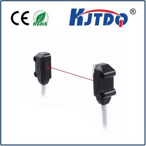
At its core, a photoelectric sensor operates by emitting a light beam (often infrared, visible red, or laser) and detecting its reflection or interruption. The sensing logic—whether it detects an object when the beam is broken (opposed mode) or when light is reflected back (retro-reflective or diffuse mode)—is separate from its electrical output type. Once the sensor's internal circuit determines an object is detected, it needs to signal this state to the controller. This is where PNP and NPN come into play. These terms refer to the type of transistor used in the sensor's output switching circuit. The choice fundamentally dictates whether the output signal provides a positive voltage (PNP) or connects to ground (NPN) when active.
A PNP sensor, also known as a "sourcing" sensor, switches the positive voltage to the output line. In a typical 24V DC system, the sensor's output wire will have 0V when idle. When an object is detected, the internal PNP transistor activates, connecting the output wire to the positive supply voltage (+24V), thus "sourcing" current to the load (like a PLC input). The load is then connected between the sensor's output and the common ground. This configuration is often the standard in many European and North American regions.
Conversely, an NPN sensor, known as a "sinking" sensor, switches the ground connection. In its idle state, the output wire is effectively floating or at a high impedance. Upon detection, the internal NPN transistor activates, connecting the output wire to the common ground (0V), thus "sinking" current from the load. Here, the load (the PLC input) must be connected between the positive supply and the sensor's output. This type is frequently used in Asian markets and in certain Japanese equipment standards.
Selecting between PNP and NPN is not a matter of sensor performance but of compatibility with the control system's input card. Most modern PLCs have input modules that can be configured for either sinking or sourcing operation, but it's essential to match the sensor to the PLC's requirements. A mismatch will result in the sensor failing to trigger the PLC input. A simple rule of thumb is: a PNP (sourcing) sensor requires a sinking PLC input, while an NPN (sinking) sensor requires a sourcing PLC input. Always consult the datasheets of both the sensor and the controller.
Wiring these sensors correctly is paramount. For a PNP sensor, the brown wire (typically) connects to +24V, the blue wire to 0V (common), and the black wire is the switched positive output. For an NPN sensor, the brown wire still connects to +24V, the blue to 0V, but the black wire becomes the switched negative (ground) output. Incorrect wiring can lead to sensor damage or a permanent "on" signal. Using a multimeter to check the voltage on the output wire in both idle and active states is a recommended troubleshooting step.
The implications of choosing PNP vs. NPN extend to system design and safety. In some safety-critical applications, a "fail-safe" logic might prefer one type over the other, depending on whether a broken wire should be interpreted as an "on" or "off" signal by the controller. Furthermore, when integrating sensors from different global suppliers into one machine, being acutely aware of this difference prevents operational headaches.
In summary, the PNP and NPN designation on a photoelectric sensor defines its electrical interfacing method, not its sensing capability. Understanding that PNP sources positive voltage and NPN sinks to ground is the key to successful integration. By carefully matching the sensor output type to the control system's input requirements and following correct wiring practices, engineers and technicians can ensure robust, reliable, and error-free operation of their automated systems, maximizing uptime and productivity.